
Multi-camera residential communication system

a communication system and multi-camera technology, applied in the field of communication systems, can solve the problems of limited appeal, lack of color imaging, and limited commercial success of picturephones

Inactive Publication Date: 2008-12-04
MONUMENT PEAK VENTURES LLC
View PDF45 Cites 160 Cited by
  • Summary
  • Abstract
  • Description
  • Claims
  • Application Information

AI Technical Summary

Problems solved by technology

However, the Picturephone had very limited commercial success.
Technical issues, including low resolution, lack of color imaging, and poor audio-to-video synchronization affected the performance and limited the appeal.
Additionally, the Picturephone imaged a very restricted field of view, basically amounting to a portrait format image of a participant.
Thus, the images were captured with little or no background information, resulting in a loss of context.
While currently many cell phones include cameras for capturing still images, most cell phones still lack live video capture and display capability.
While phone-cameras are easy to use, highly mobile, and have arguably become essential for modern life, the size and cost structure constraints limit their applicability for some uses.
While these video-camera-computer systems are enabling internet-based video-telephony, these technologies have not become ubiquitous like the cell phone has.
Certainly, the differential increased cost and size are reasons for this.
However, there are many issues related to the user experience with the web-camera that have not yet been adequately addressed.
In particular, these systems are not fully optimized for easy use in dynamic environments, such as the home.
However, the WebEx approach, while useful, does not anticipate the concerns people have when communicating by video on a personal basis.
However, there are many aspects of residential video-telephony, relative to managing privacy and personal context in a dynamic residential environment that this system does not anticipate.
While Chim '258 suggests that this system might be used in a residential environment, in most respects, the system is really targeted for the corporate conference room environment, as the privacy and context management aspects are underdeveloped.
As image capture occurs in structured environments with known participants behaving in relatively formalized ways, these conference systems are not enabled with capabilities that could be desired in the dynamic personal environments.
Additionally, the cost of teleconferencing systems is often in excess of $100,000, which is not supportable by the residential market.
Thus, they are not sufficiently adaptive to residential dynamics, and the privacy and context management aspects are underdeveloped.
'431 approach does not provide a sufficiently versatile approach for a user control the privacy of their environment, or for themselves or others (such as family members).
This system also lacks contextually interpretive controls and features that would be useful in a residential environment.
Although such systems enabled informal communications as compared to the conference room setting, these systems were developed for work use, rather than personal use in the residential environment, and thus do not anticipate residential concerns.
The authors recognize that personal privacy concerns are much more problematic for home users than for office based media spaces.
As the paper discusses, privacy encroaching circumstances can arise when home users forget that the system is on, or other individuals unwarily wander into the field of view.
However, while this system is located in the home, it is not intended for personal communications by the residents.
As such, it does not represent a residential communication system that can adapt to the personal activities of one or more individuals, while aiding these individuals in maintaining their privacy.

Method used


Image

  • Multi-camera residential communication system
  • Multi-camera residential communication system
  • Multi-camera residential communication system

Examples


Embodiment Construction

[0034]The quality of video teleconferencing or video telephony is loosely described today by the term “telepresence”, which has been defined as the experience or impression of being present at a location remote from one's own immediate environment. This term has been particularly applied to corporate teleconferencing, relative to enabling teams who cannot be together, work together. The video-conferencing systems that provide eye-contact life size images of the remote participants, with the remote background extracted, such that the remote participants appear as if they are in the local environment, are perhaps an idealized implementation of a telepresence system. However, in some sense, the telepresence concept is a misnomer, as the various controls and tools, including camera zoom, can create an artificial experience, which is in some respects equivalent to “better than being there”.

[0035]While the telepresence concept may be useful for residential video-telephony, it is not neces...


PUM


Abstract

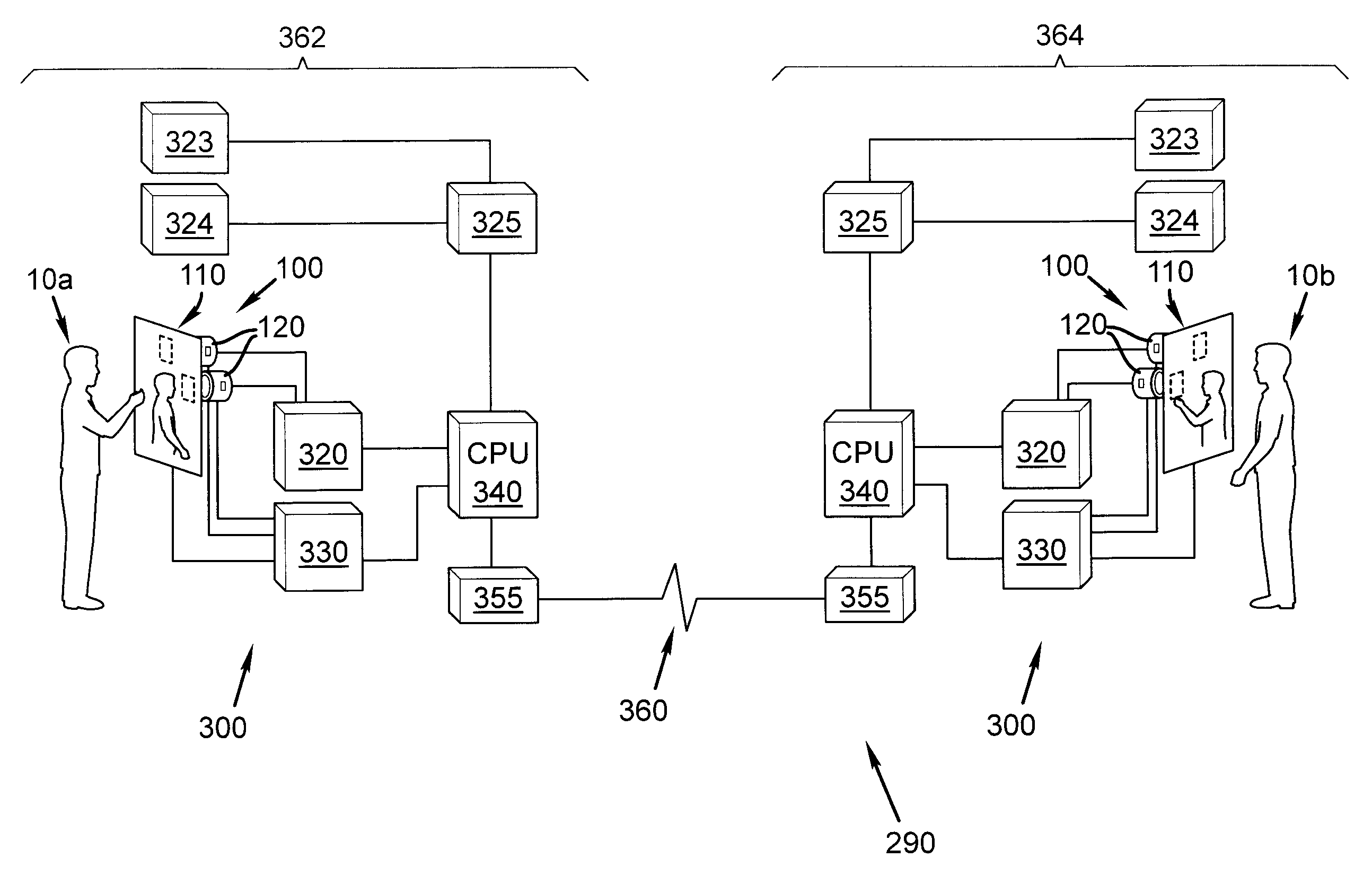
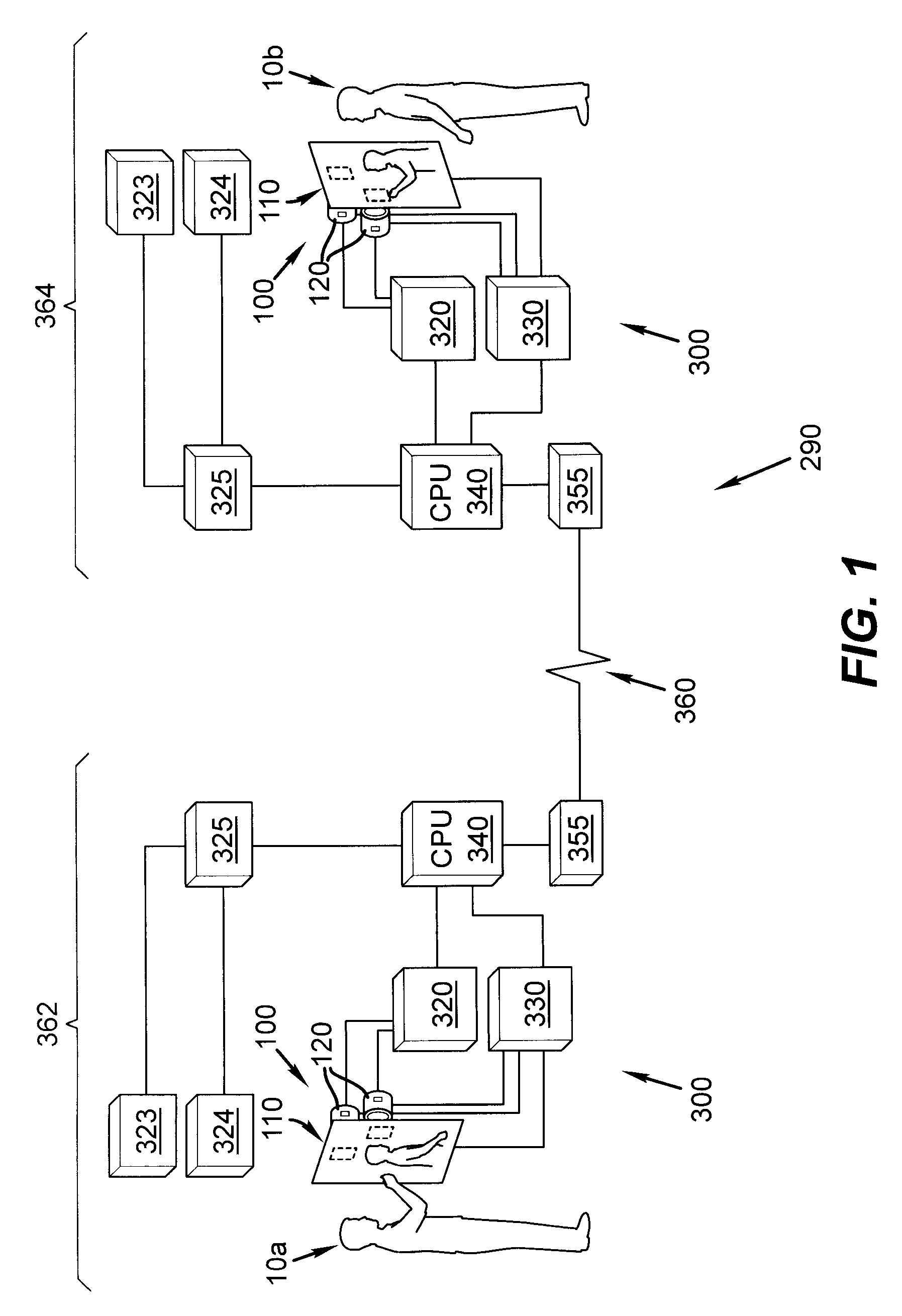
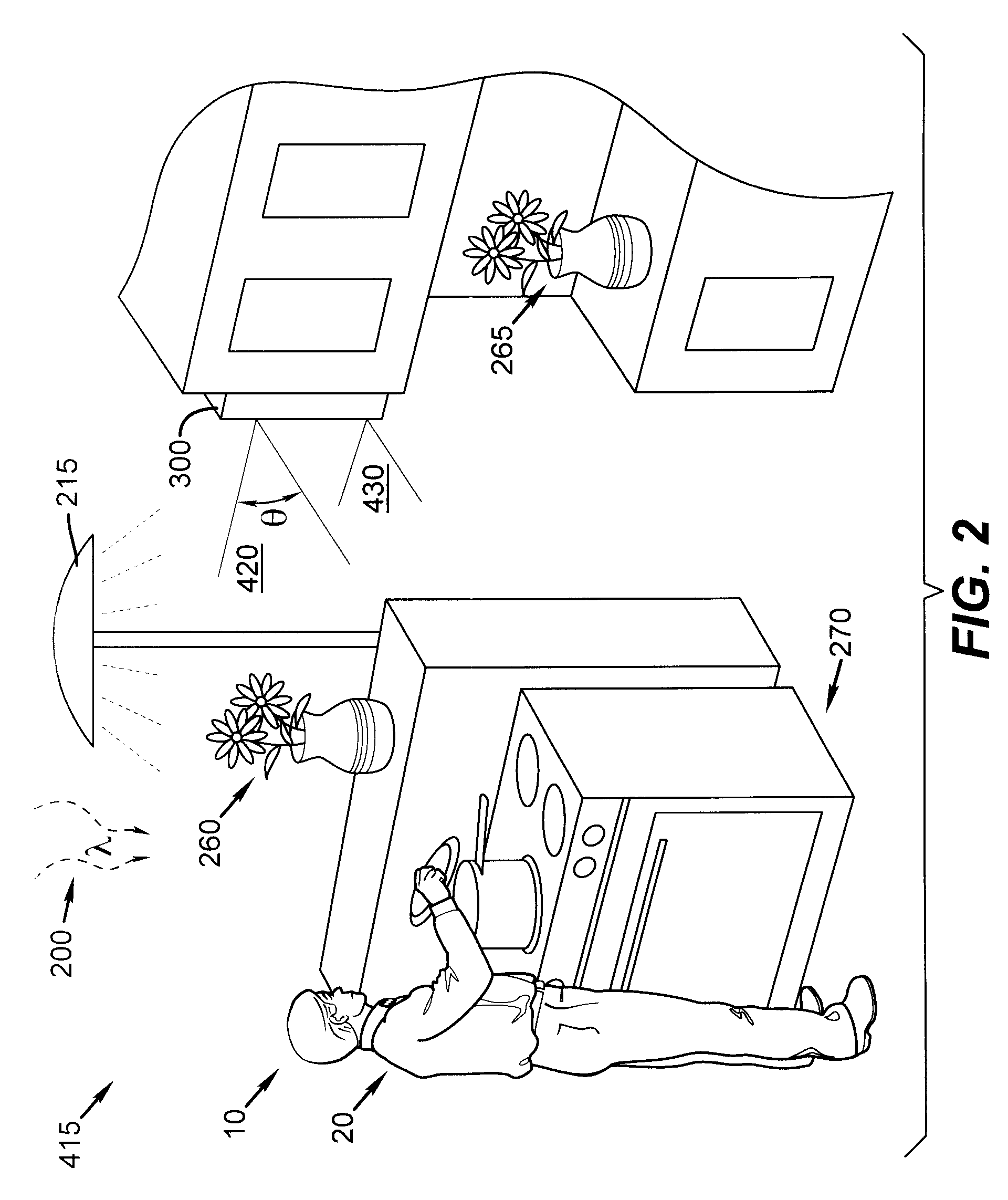
Video communication devices and methods are provided. The device has an image display device; a first image capture device that acquires video images depicting a wide field of view within the local environment; a second image capture device that acquires video images depicting a narrow field of view within the wide field of view; a communication system that is adapted to use a communication network to transmit outgoing video images; and a computer causing the capture of video images during a communication event, and further being adapted to identify a video context for the communication event; wherein said computer uses a scene analysis algorithm to examine concurrent video images from the image capture device based upon the identified video context to determine the extent to which video images from the first image capture device and the second image capture device are to be incorporated into the outgoing video images.

Description

CROSS REFERENCE TO RELATED APPLICATIONS[0001]This application is related to U.S. Ser. No. (Attorney Docket 93639), entitled A RESIDENTIAL VIDEO COMMUNICATION SYSTEM in the name of Kurtz et al.; U.S. Ser. No. (Attorney Docket 94020), entitled MANAGING SCENE TRANSITIONS FOR VIDEO COMMUNICATION, in the name of Kurtz et al., U.S. Ser. No. (Attorney Docket 94021), entitled PERSONAL CONTROLS FOR PERSONAL VIDEO COMMUNICATIONS, in the name of Kurtz et al.; and U.S. Ser. No. (Attorney Docket 94023), entitled EYE GAZE IMAGING FOR VIDEO COMMUNICATIONS in the name of Kurtz et al. all filed concurrently herewith.[0002]Reference is also made to commonly-assigned copending U.S. patent application Ser. No. 11 / 555,822, filed Nov. 2, 2006, entitled “An Integrated Display Having Multiple Capture Devices”, by Kurtz et al., the disclosure of which is incorporated herein.FIELD OF THE INVENTION[0003]The present invention relates to communication systems that enable video communications between remote and ...

Claims


Application Information

Patent Timeline
Patent Type & Authority Applications(United States)
IPC IPC(8): H04N7/14
CPCG06K9/00335H04N7/142H04N7/15G06V40/20
Inventor KURTZ, ANDREW F.BORDER, JOHN N.
Owner MONUMENT PEAK VENTURES LLC
Learn More