Optical apparatus having device for removing foreign substance

Active Publication Date: 2008-12-04
CANON KK
View PDF6 Cites 18 Cited by
  • Summary
  • Abstract
  • Description
  • Claims
  • Application Information

AI Technical Summary

Benefits of technology

[0017]The present invention is directed to an optical apparatus having a structure for removing a foreign substance, which can miniaturize

Problems solved by technology

Consequently, visual quality of the image deteriorates.
In addition, when the lens is changed, a foreign substance, such as dust, may enter the camera body from an opening of a lens mount and may adhere to the surface of the image sensor or the filter.
Thus, a space to be wasted in design of the finder optical system is needed.
In addition, there is a fear of reduction in optical performance of the camera.
The first camera discussed in U.S. Pat. No. 7,006,138 has a relatively high cost, because the two piezoelectric elements are attached along a pair of parallel sides of the rectangular optica

Method used


Image

  • Optical apparatus having device for removing foreign substance
  • Optical apparatus having device for removing foreign substance
  • Optical apparatus having device for removing foreign substance

Examples


Example

[0040]Various exemplary embodiments, features, and aspects of the invention will be described in detail below with reference to the drawings.

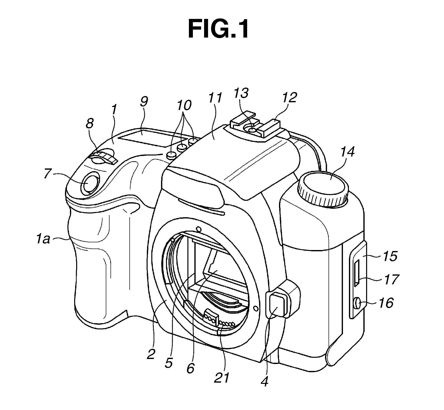
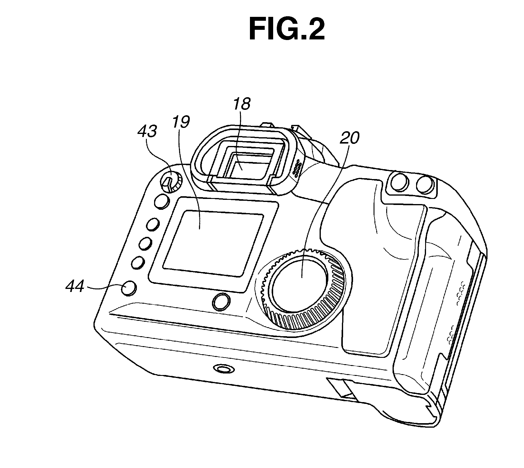
[0041]A digital single-lens reflex camera according to an exemplary embodiment of the present invention is described first with reference to FIGS. 1 through 3. FIGS. 1 and 2 illustrate an appearance of the digital single-lens reflex camera according to the exemplary embodiment of the present invention. FIG. 1 is a perspective view of the camera, which is taken from a front side (subject side) thereof. FIG. 1 illustrates the camera from which a photographic lens unit is removed. FIG. 2 is a perspective view of the camera, which is taken from a photographer side (rear side).

[0042]As illustrated in FIG. 1, a camera body 1 has a grip portion 1a protruding towards a subject so that a photographer can stably hold the camera during photographing.

[0043]A photographic lens unit 200a (see FIG. 3) is removably mounted on a lens mount 2 of the camera body ...


PUM


Abstract

An optical apparatus includes a rectangular optical member provided on an optical axis, and a rectangular vibrating device stuck to the optical member close to and in parallel with one of four sides of the optical member and configured to vibrate the optical member in a wave fashion to have a plurality of nodes parallel with the one side. The vibrating device is configured to operate in two or more vibration modes differing from one another at least in number or positions of the plurality of nodes.

Description

CROSS-REFERENCE TO RELATED APPLICATIONS[0001]The present application is related to U.S. patent application Ser. No. ______, filed on ______ (see also Attorney Docket No. 10043687US01).[0002]Moreover, the present application is also related to U.S. patent application Ser. No. ______, filed on ______ (see also Attorney Docket No. 10053057US01).[0003]This application claims priority from Japanese Patent Application No. 2007-146018 filed May 31, 2007, which is hereby incorporated by reference herein in its entirety.BACKGROUND OF THE INVENTION[0004]1. Field of the Invention[0005]The present invention relates to a technology for removing a foreign substance, such as dust, adhering to a surface of an optical member provided on an optical axis of an optical apparatus, such as an imaging apparatus.[0006]2. Description of the Related Art[0007]In imaging apparatuses, such as digital cameras, which perform imaging of a subject by converting a subject image into an electrical signal, an imaging ...

Claims


Application Information

Patent Timeline
IPC IPC(8): H04N5/225
CPCG02B27/0006G03B17/14G03B17/28H04N5/2254H04N23/811H04N23/55
Inventor URAKAMI, TOSHIFUMIKAIHARA, SHOJI
Owner CANON KK
Why Eureka
Try Eureka