Optical Cable and Method for Producing an Optical Cable

a technology of optical cable and optical cable, applied in the field of optical cable, can solve the problems of high-viscosity gel only deforming very slowly, sheath absorbs compound, and is difficult to achieve the effect of preventing water from spreading

Inactive Publication Date: 2008-12-04
CCS TECH INC
View PDF10 Cites 8 Cited by
  • Summary
  • Abstract
  • Description
  • Claims
  • Application Information

AI Technical Summary

Benefits of technology

[0042]The object of the invention is also to specify a method for producing an optical cable of which the optical transmis

Problems solved by technology

However, an interaction may occur between components of the buffered-fiber filling compound and the matrix polymer of the buffer tube, with the consequence that the sheath absorbs compound by migration.
However, a high-viscosity gel can only deform very slowly.
This has the effect, for example, that

Method used


Image

  • Optical Cable and Method for Producing an Optical Cable
  • Optical Cable and Method for Producing an Optical Cable
  • Optical Cable and Method for Producing an Optical Cable

Examples


Embodiment Construction

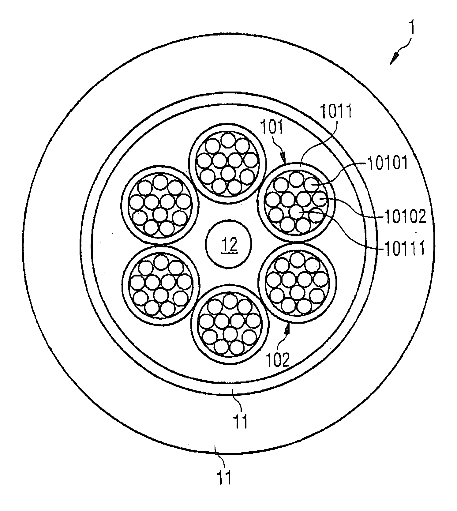
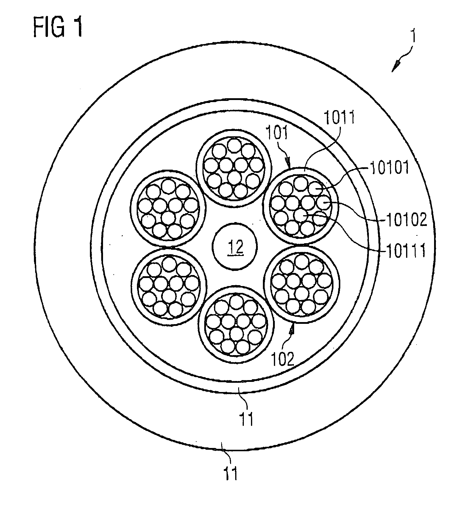
[0066]In FIG. 1, an optical cable according to a first exemplary embodiment of the present invention is represented. The optical cable 1 comprises the cable sheath 11, which surrounds the interior of the cable, referred to as the cable core. The cable sheath 11 comprises materials such as polyethylene (PE), polypropylene (PP) or polyamide (PA). Furthermore, the optical cable 1 contains the optical transmission elements 101 and 102, which are arranged within the cable sheath 11. The optical transmission element 101 comprises the buffer tube 1011. The buffer tube 1011 contains a matrix polymer such as polyvinyl chloride or ethyl vinyl acetate, in which a passive filler such as chalk is embedded. The elongation at break or tensile strength of the buffer tube 1011 can be set by means of the percentage by mass of the filler. The elongation at break is preferably set low, in order that the buffer tube 1011 can be removed without special tools. The optical transmission element 101 also com...


PUM

PropertyMeasurementUnit
Fractionaaaaaaaaaa
Fractionaaaaaaaaaa
Transmissionaaaaaaaaaa

Abstract

An optical cable (1) comprises a cable sheath (11) and at least two optical transmission elements (101) and (102), which are arranged within the cable sheath (11). One (101) of the optical transmission elements (101) and (102) comprises a buffer tube (1011), at least one optical waveguide (10101) and at least one swelling element (10111). The buffer tube (1011) surrounds the at least one optical waveguide (10101) and the at least one swelling element (10111). The swelling element (10111) comprises a swelling material, which can swell by supplying it with water. If water penetrates into the optical transmission element, the swelling element (10111) swells and seals off the optical transmission element, so that spreading of the water in the longitudinal direction of the optical transmission element is prevented.

Description

FIELD OF INVENTION[0001]The invention relates to an optical cable with optical transmission elements, which have a buffer tube with low elongation at break. The invention also relates to a method for producing an optical cable with which a good longitudinal water tightness of optical transmission elements can be achieved.BACKGROUND OF THE INVENTION[0002]An optical cable, which may be intended for the construction of a broadband communications network, contains a large number of optical waveguides. In general, the optical cable contains a number of optical transmission elements, which are also referred to as buffered fibers or “units”. Each of the optical transmission elements contains a number of optical waveguides.[0003]For example, the optical cable may contain 12 optical transmission elements and each of the optical transmission elements may contain 12 optical waveguides.[0004]Furthermore, the optical cable comprises a cable sheath and a cable core. The cable sheath surrounds the...

Claims


Application Information

Patent Timeline
IPC IPC(8): G02B6/44C03C25/10
CPCG02B6/4494G02B6/441G02B6/44384
Inventor WUNSCH, GUNTERKAMPS, RAINER
Owner CCS TECH INC
Why Eureka
Try Eureka