Centrifuge

a centrifuge and centrifugal technology, applied in the field of centrifuges, can solve the problems of poor centrifugal operation efficiency, insufficient bath sterilization, corrode or degenerate the composing parts, etc., and achieve the effect of easy opening and closing, easy realization and simple

Active Publication Date: 2008-12-04
EPPENDORF HIMAC TECH CO LTD
View PDF23 Cites 24 Cited by
  • Summary
  • Abstract
  • Description
  • Claims
  • Application Information

AI Technical Summary

Benefits of technology

[0034]According to such a configuration, since at least one of the two opening/closing valves is formed as a power valve, and there is provided control means for controlling the power valve, a desired one o

Problems solved by technology

However, in the centrifuge, such steam sterilization is not enforced owing to the structural limit thereof and owing to the limit of the material of the parts thereof, but there is employed exclusively a method for sterilizing the centrifuge using a bath.
The bath sterilization is not sufficient, because some of baths have no effect on some of bacteria and various kinds of minor germs.
Also, when such bacteria and minor germs come into contact with the composing parts of the centrifuge, it has been found that they can corrode or degenerate the composing parts.
Thus, it takes long time to cool the cylindrical rotor fr

Method used


Image

  • Centrifuge
  • Centrifuge
  • Centrifuge

Examples


embodiment 1

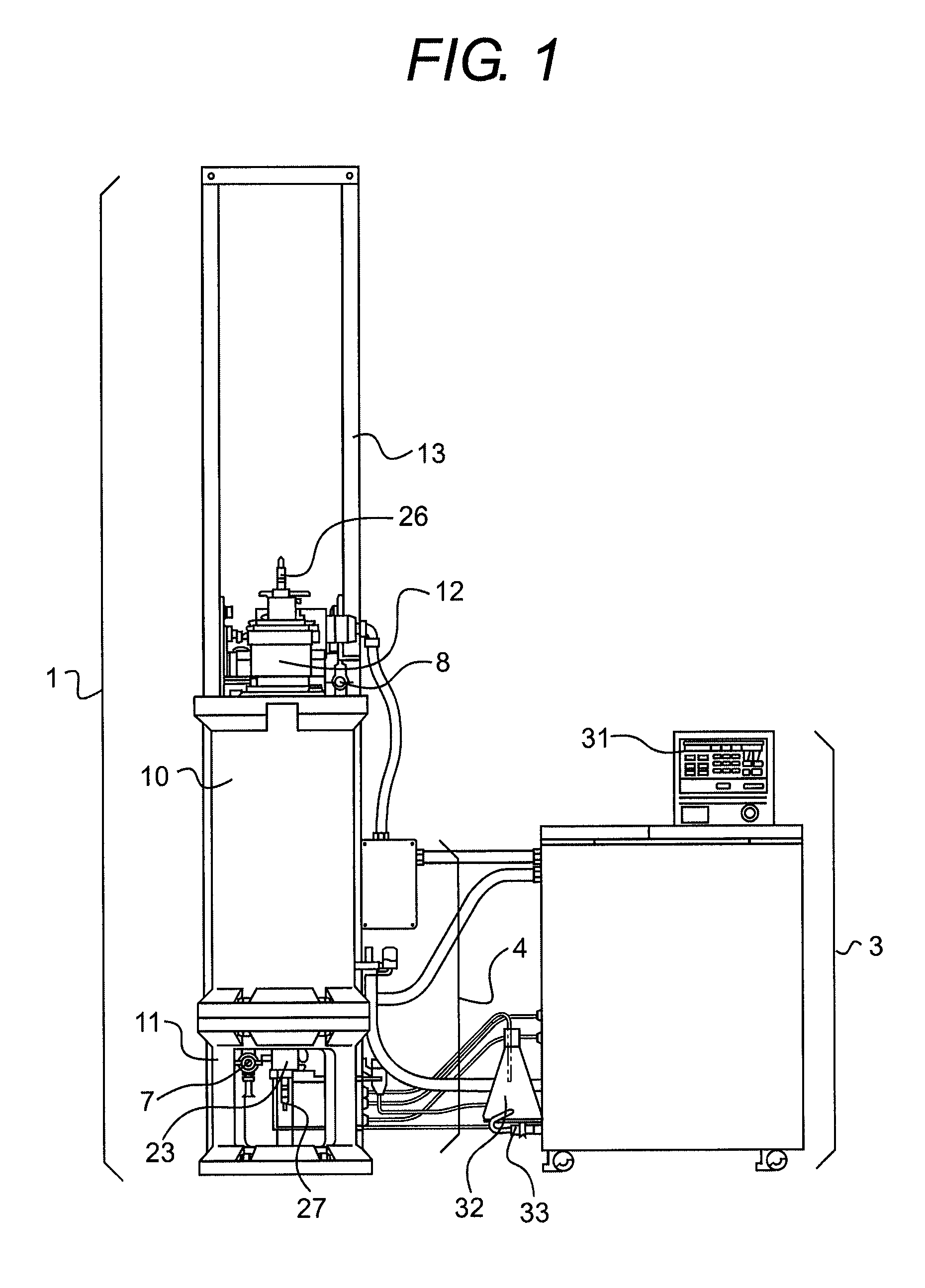
[0046]FIG. 1 is a front view of a centrifuge according to an embodiment 1. In FIG. 1, the rotation device portion 1 of the present centrifuge is fixed to a floor using a bolt, and, on the right of the rotation device portion 1, there is installed a control device portion 3 with a given distance therefrom, while the rotation device portion 1 and control device portion 3 are connected to each other by various connecting pipes / electrical wires 4.

[0047]The control device portion 3 includes a control panel 31 provided on the upper portion thereof. The control panel 31 has a function for setting the speed of revolutions, rotation time, temperature and the like which are the operating conditions of the present centrifuge, a function for displaying the operating state of the centrifuge, a start / stop switch used to operate the centrifuge, and other functions. Also, the control device portion 3 further includes in the inside thereof: a power source (for example, an inverter) for a drive porti...

embodiment 2

[0065]Next, description will be given below of an embodiment 2 according to the invention with reference to FIG. 6.

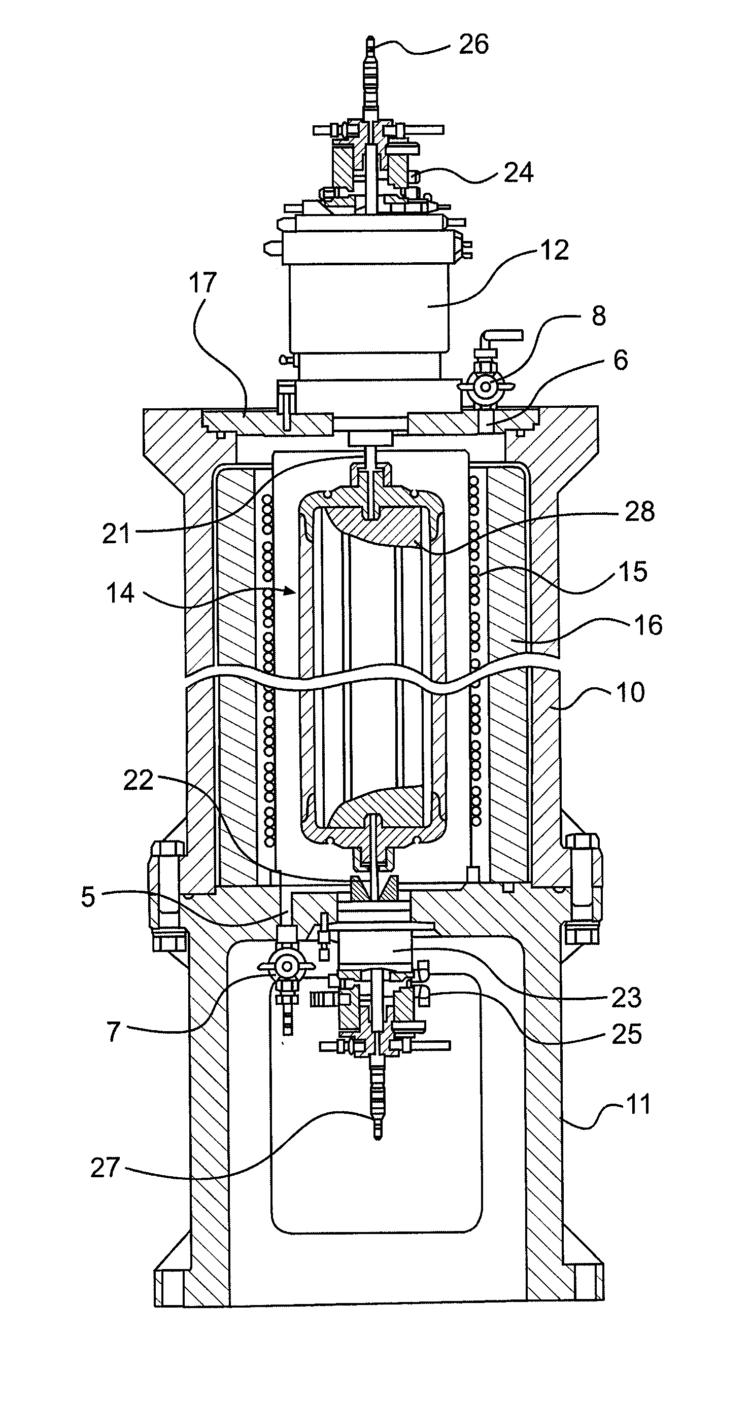
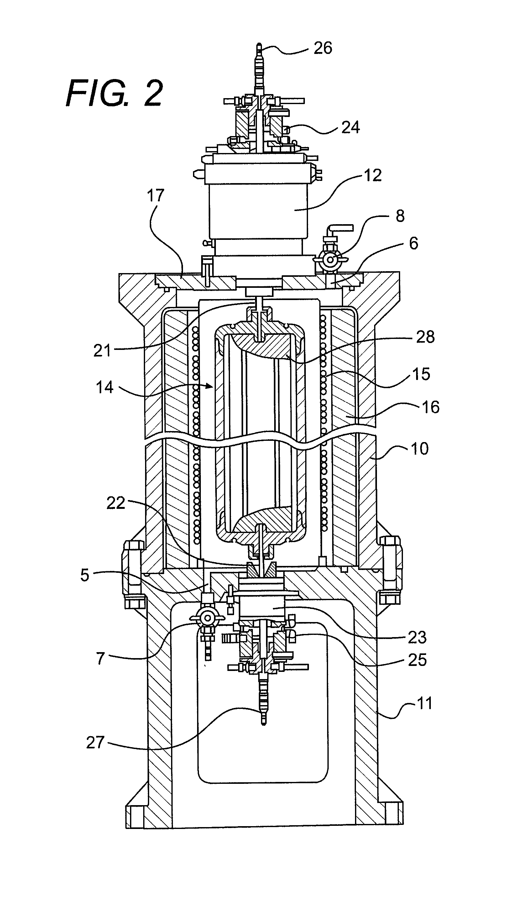
[0066]FIG. 6 is a front section view of a rotation device portion of a centrifuge according to an embodiment 2. In FIG. 6, the same elements as those shown in FIGS. 1˜4 are given the same designations and thus duplicate description thereof will be omitted below.

[0067]A centrifuge according to the present embodiment is characterized by an air filter 9 which is provided on the open end of the upper valve 8 disposed on the upper plate 17 mounted on the upper portion of the chamber 10, while the structures of the remaining portions of the present embodiment are similar to those of the previously described embodiment 1.

[0068]The sample to be treated in a continuous centrifuge, as described above, is produced from a living thing such as a virus, a bacterium or the like, and thus there is a possibility that the sample can be dangerous to the operator of the centrifuge and pers...

embodiment 3

[0072]Next, description will be given below of an embodiment 3 according to the invention with reference to FIG. 7.

[0073]FIG. 7 is a front section view of a rotation device portion included in a centrifuge according to an embodiment 3, in which the same elements as those shown FIG. 6 are given the same designations and thus the duplicate description thereof will be omitted here.

[0074]According to the present embodiment, a pipe 34 is connected to the upper valve 8 provided on the upper plate 17 disposed upwardly of the chamber 10, the pipe 34 is penetrated through a partition wall 36 and is extended externally of the outside 37 of a centrifuge installation room, and the open end 35 of the pipe 34 is opened to the room outside 37, whereby a gas for cooling introduced into the chamber 10 is discharged from the pipe 34 to the room outside 37. The structures of the remaining portions of the present embodiment are the same as those employed in the previously described embodiments 1 and 2....


PUM


Abstract

According to an aspect of the present invention, there is provided a centrifuge in which a steam sterilization of a sample flow passage is performed, the centrifuge including: a rotor configured to centrifuging a liquid sample; a drive portion that drives and rotates the rotor; a chamber that accommodates the rotor therein, the chamber having a first and a second penetration holes provided on an upper and a bottom portions thereof, respectively; and a first and a second valves disposed on the first and the second penetration holes, respectively; wherein a cooling gas is introduced through one of the first and the second penetration holes and discharged through the other to cool a periphery of the rotor before or after execution of a centrifuging operation of the liquid sample.

Description

CROSS-REFERENCE TO RELATED APPLICATIONS[0001]This application is based upon and claims a priority from prior Japanese Patent Application No. 2007-144677 filed on May 31, 2007, the entire contents of which are incorporated herein by reference.BACKGROUND OF THE INVENTION[0002]1. Field of the Invention[0003]An aspect of the present invention relates to a centrifuge which, while charging a liquid sample continuously into a rotor, rotates the rotor at a high speed to centrifuge micro-particles contained in the liquid sample.[0004]2. Description of the Related Art[0005]As a centrifuge of this type, there are known a centrifuge which is disclosed in the JP-UM-S48-028863-B for centrifuging a virus contained in a liquid medium, and continuous centrifuges respectively disclosed in the JP-H07-106328-B and JP-2004-322054-A in which a sample to be centrifuged is centrifuged in a state where it is isolated from the open air.[0006]Here, description will be given below of a conventional centrifuge ...

Claims


Application Information

Patent Timeline
IPC IPC(8): B04B15/02
CPCB04B7/02B04B15/02B04B15/06
Inventor AKATSU, KATSUNORIAIZAWA, MASAHARUKONNO, TATSUYA
Owner EPPENDORF HIMAC TECH CO LTD
Why Eureka
Try Eureka