Expandable Interbody Fusion Device

a fusion device and expandable technology, applied in the field of expandable interbody fusion devices, can solve the problems of affecting the inability to implant a rod or plate during fusion, and the inability to maintain the stability of the fusion level, so as to prevent the disengagement of the wafer

Active Publication Date: 2008-12-04
SPINEWAVE
View PDF79 Cites 344 Cited by
  • Summary
  • Abstract
  • Description
  • Claims
  • Application Information

AI Technical Summary

Benefits of technology

[0014]In one embodiment, the wafers are like-configured, each comprising an interlocking engagement that includes a plurality of resiliently deflectable prongs that project above an upper surface of the wafer, and a like plurality of locking surfaces extending transversely between the upper surface and the lower surface. The prongs deflect as each wafer is inserted into the space between the expandable upper and lower plates until each wafer is substantially co-extensive with the prior inserted wafer. When so oriented, the prongs resiliently deflect upward against corresponding locking surfaces to prevent retrograde movement (i.e., opposite the direction of insertion) of the newly inserted wafer.
[0015]Each wafer is configured with angled leading and trailing ends so that each newly inserted wafer lifts the stack of prior inserted wafers. As each wafer is inserted, additional interlocking features are engaged that prevent movement of the wafers in other degrees of freedom. One interlocking feature includes a keyway and tab arrangement that prevents further movement along the direction of insertion. Yet another interlocking feature prevents relative movement transverse to the insertion direction and vertically within the stack of wafers. The interlocking features also prevent disengagement of the wafers or dislodgement of any wafer from the stack due to torsional or twisting movement.

Problems solved by technology

Since the damaged disc material has been removed, something must be positioned within the intra-discal space, otherwise the space may collapse resulting in damage to the nerves extending along the spinal column.
With this technique, once fusion has occurred the hardware used to maintain the stability of the segment became superfluous.
Moreover, the surgical procedures necessary to implant a rod or plate to stabilize the level during fusion were frequently lengthy and involved.
These “interbody fusion devices” have taken many forms, but many have had difficulty in achieving fusion, at least without the aid of some additional stabilizing device, such as a rod or plate.
Moreover, some of these devices are not structurally strong enough to support the heavy loads and bending moments applied at the most frequently fused vertebral levels, namely those in the lower lumbar spine.
The interbody fusion devices (IBFDs) that have overcome these difficulties are typically bulky, at least with respect to the intervertebral space.
One drawback of this approach is that the implant device is not exactly sized to the anatomy of the particular patient, thus typically requiring pre-distraction of opposed vertebrae in order to increase the disc space for device implantation.
While a collection of differently sized IBFDs can be provided, it is unwieldy and impractical to provide an IBFD sized for every intervertebral disc space height.
Another drawback of these prior devices is that the surgical insertion site must be at least as big as the IBFD.
The distracted space is subjected to significant loads, even when efforts are made to immobilize the spine around the affected vertebral level.

Method used


Image

  • Expandable Interbody Fusion Device
  • Expandable Interbody Fusion Device
  • Expandable Interbody Fusion Device

Examples


Embodiment Construction

[0037]For the purposes of promoting an understanding of the principles of the invention, reference will now be made to the embodiments illustrated in the drawings and described in the following written specification. It is understood that no limitation to the scope of the invention is thereby intended. It is further understood that the present invention includes any alterations and modifications to the illustrated embodiments and includes further applications of the principles of the invention as would normally occur to one skilled in the art to which this invention pertains.

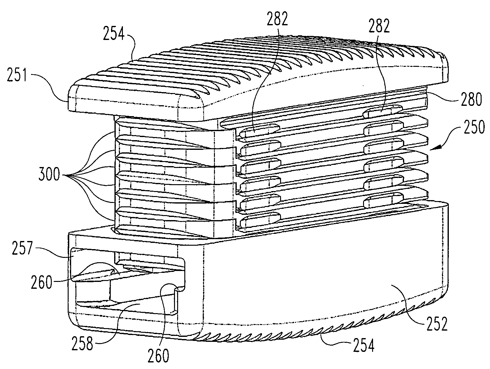
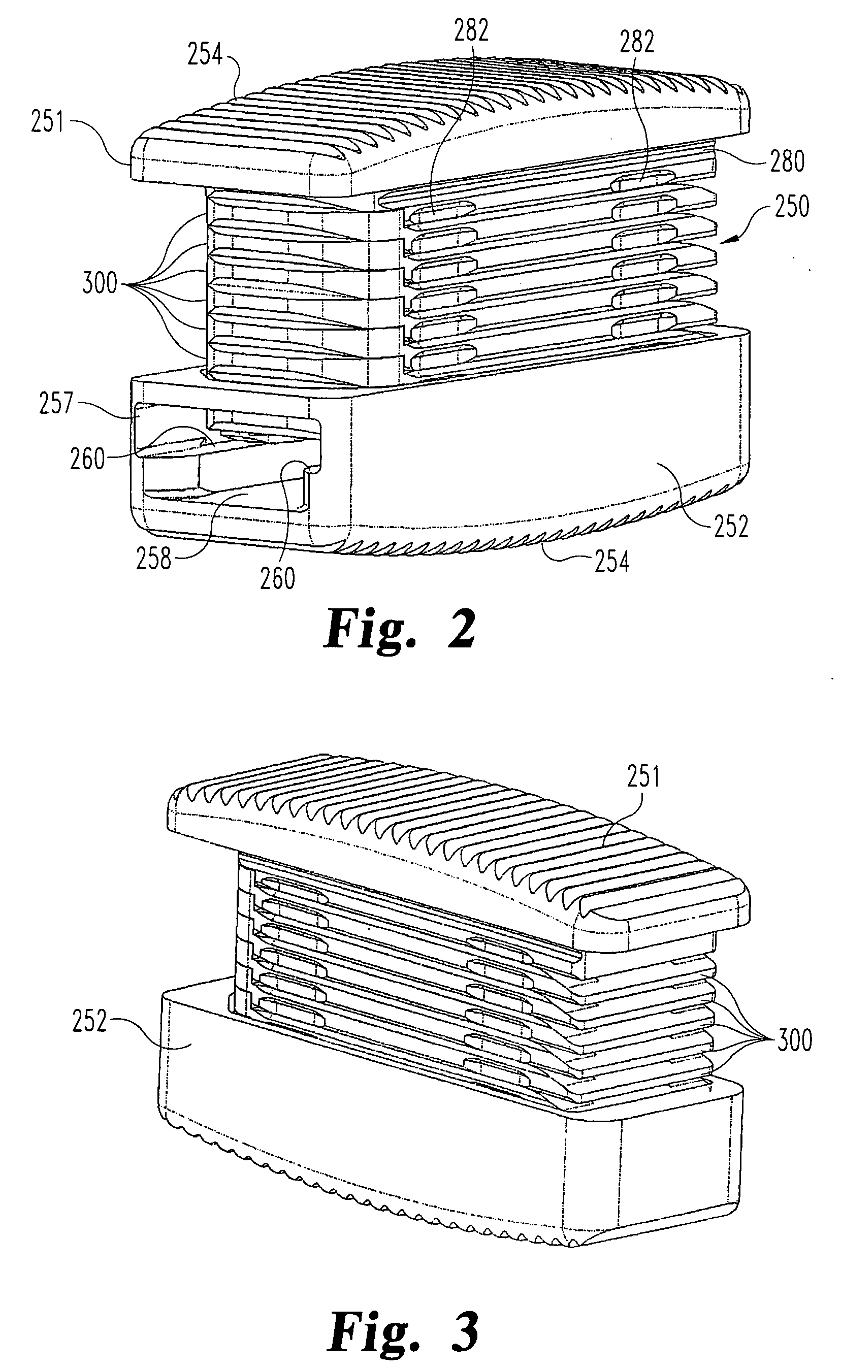
[0038]The present invention contemplates an improved interlocking wafer, and particularly a wafer configuration that firmly and permanently interlocks a stack wafers inside an expandable distraction device, even when subjected to normal spinal loads. In accordance with one embodiment of the invention, an expandable distraction device 250 is provided, as shown in FIGS. 2-5, which includes a stack of interlocking ...


PUM


Abstract

An expandable interbody fusion device includes superior and inferior endplates that are configured to receive a sequentially inserted stack of interlocking expansion members or wafers. The like-configured wafers include features on their top and bottom surfaces that interlock the wafers in multiple degrees of freedom so that the wafer stack is not disrupted when the fusion device is fully expanded. One of the interlocking features includes a plurality of prongs projecting from an upper surface of the wafers and into a recess defined in the lower surface of an adjacent previously inserted like-configured wafer. The prongs and recesses are configured to prevent retrograde movement of each new wafer in a direction opposite the direction of insertion. Other interlocking features prevent movement in the direction of insertion, transverse to the insertion direction and vertically within the stack.

Description

BACKGROUND OF THE INVENTION[0001]The present invention relates to devices and methods for distraction and stabilization of tissue surfaces, and most particularly for stabilization of the intervertebral disc space in interbody fusion applications.[0002]The number of spinal surgeries to correct the causes of low back pain has steadily increased over the last several years. Most often, low back pain originates from damage or defects in the spinal disc between adjacent vertebrae. The disc can be herniated or can be suffering from a variety of degenerative conditions, so that in either case the anatomical function of the spinal disc is disrupted. The most prevalent surgical treatment for these types of conditions has been to fuse the two vertebrae surrounding the affected disc. In most cases, the entire disc will be removed, except for the annulus, by way of a discectomy procedure. Since the damaged disc material has been removed, something must be positioned within the intra-discal spac...

Claims


Application Information

Patent Timeline
Patent Type & Authority Applications(United States)
IPC IPC(8): A61F2/44A61B17/58
CPCA61F2/30965A61F2/4455A61F2/4611A61F2/4637A61F2002/305A61F2002/30522A61F2002/3055A61F2002/30551A61F2002/30579A61F2002/30599A61F2002/30604A61F2002/30904A61F2002/4642A61F2220/0025A61F2250/0063A61F2/442A61F2/447A61F2/30771A61F2/4425A61F2002/30403A61F2002/30428A61F2002/30574
Inventor BARREIRO, PETERTY, DENNISLANDRY, MICHAEL E.
Owner SPINEWAVE
Why Eureka
Try Eureka