Method of combining heat pipe and fins and the assembly thereof

a technology which is applied in the direction of lighting and heating apparatus, semiconductor/solid-state device details, soldering apparatus, etc., can solve the problems of tin affecting the defective ratio of manufacture, the contact area of heat pipe and fins is important, etc., and achieves the effect of fast and easy combination

Inactive Publication Date: 2008-12-11
TAI SOL ELECTRONICS
View PDF0 Cites 11 Cited by
  • Summary
  • Abstract
  • Description
  • Claims
  • Application Information

AI Technical Summary

Benefits of technology

[0008]The primary objective of the present invention is to provide a method of combining heat pipe and fins and the assembly thereof, which provides a faster and easier way of combination of the heat pipe and fins.

Problems solved by technology

The contact area of the heat pipe and the fins is an important issue.
The escape of the tin will affect the defective ratio of manufacture.

Method used


Image

  • Method of combining heat pipe and fins and the assembly thereof
  • Method of combining heat pipe and fins and the assembly thereof
  • Method of combining heat pipe and fins and the assembly thereof

Examples


Embodiment Construction

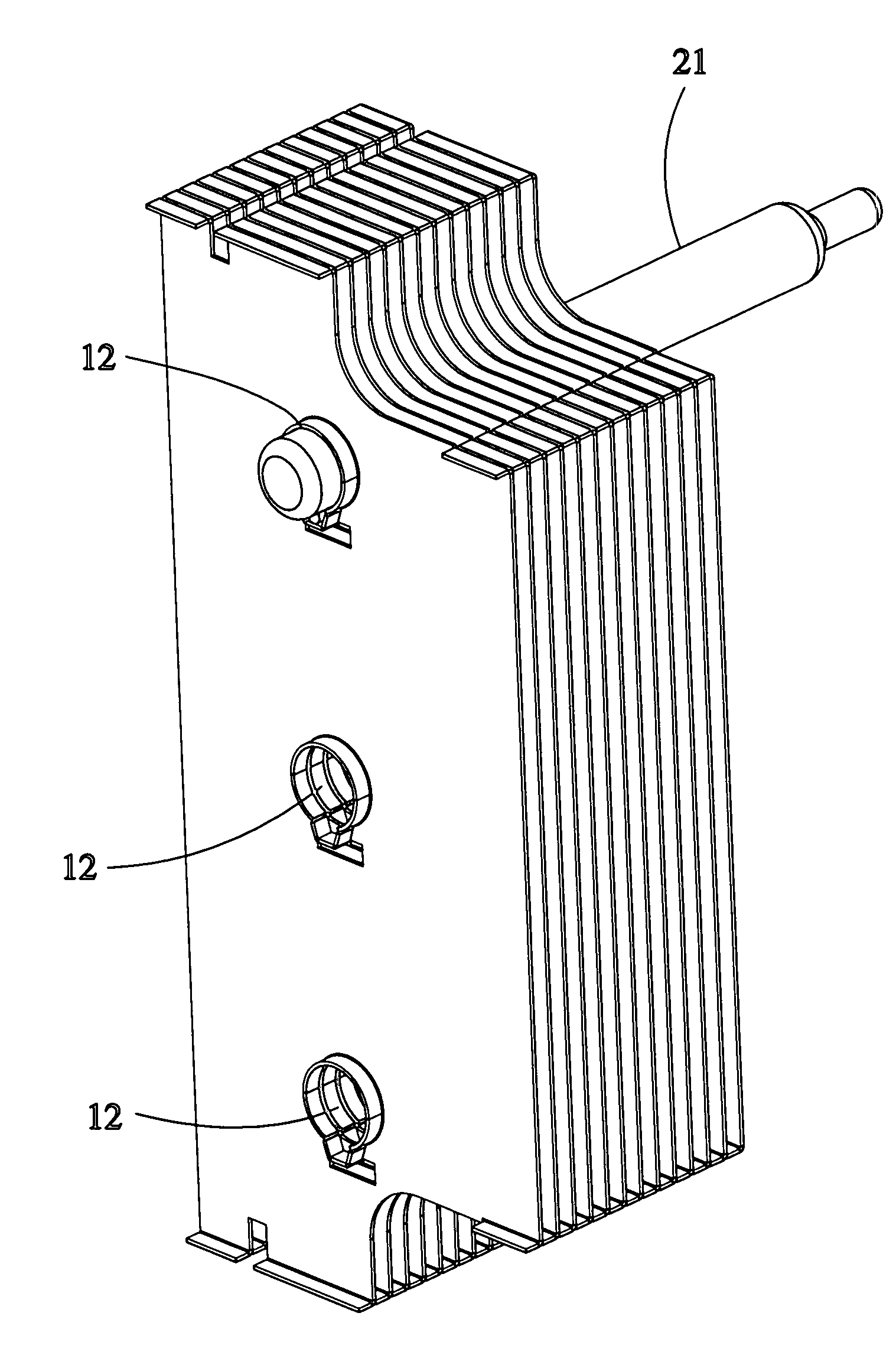
[0021]The present invention only provides one heat pipe 21 inserted into through hole 12.

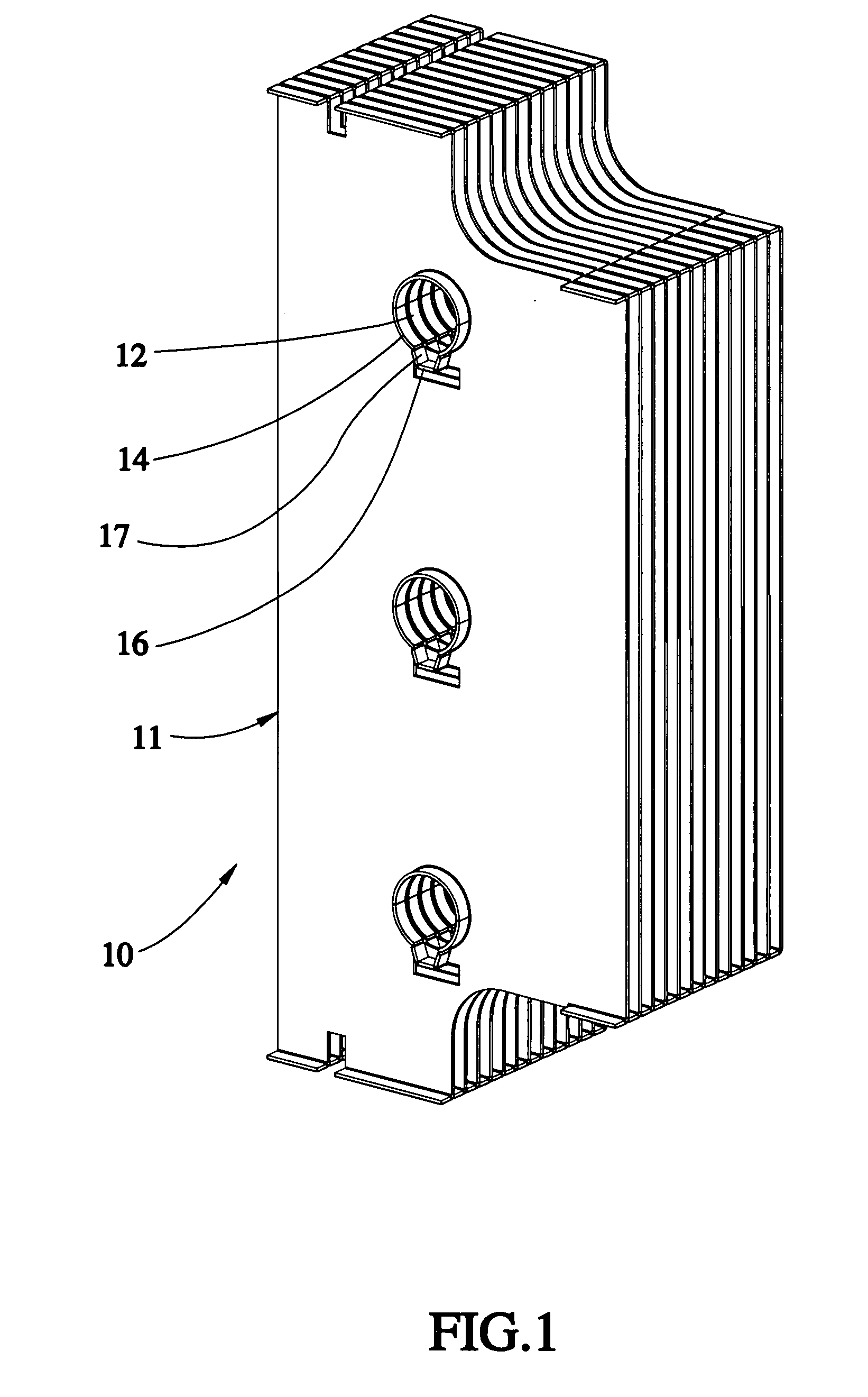
[0022]As shown in FIG. 1 to FIG. 7, a method of the first preferred embodiment of the present invention includes the following steps:

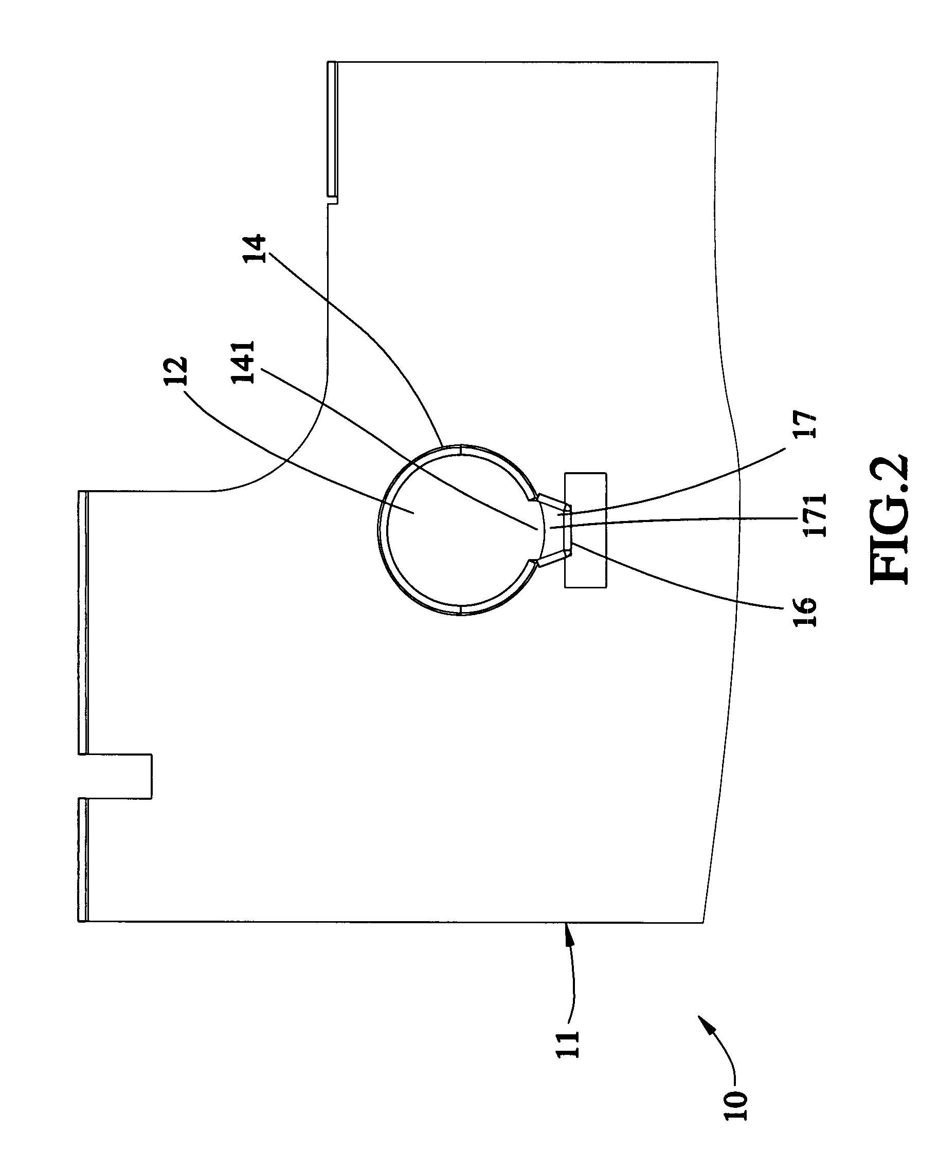
[0023]a) Preparation of a plurality of fins 11 and heat pipes 21: The fins 11 are stacked, each of which has a plurality of holes 12. The heat pipes 21 may pass through the holes 12 of the fins 11 respectively. Each of the fins 11 has an extending wall 14 around each of the holes 12 respectively. Each of the extending walls 14 has a first opening 141. Each of the fins 11 has a lateral plate 16 in front of each of the first opening 141 of the extending wall 14. Each of the lateral plate 16 has a receiving portion 17 with a second opening 171 aligned with the first opening 141. The fins 11 are against distal ends of the extending walls 14 and lateral plates 16 of the neighboring fins 11. The extending walls 14 and the lateral plates 16 on each of the fins 11 have the...


PUM

PropertyMeasurementUnit
widthsaaaaaaaaaa
surface areaaaaaaaaaaa
areaaaaaaaaaaa

Abstract

The present invention provides a method of combining heat pipes and fins and the assembly thereof. The fins are stacked, each of which has holes, extending walls around the holes, lateral plates beside the extending walls to form a receiving portion therein communicated with a first opening of the extending wall respectively. The fins are placed with the receiving portions under the holes first. A solder material is injected into the receiving portions by a needle. The heat pipes are inserted into the holes of the fins, and then the fins are tipped over to have the receiving portions above the holes. Now the fins are heated to melt the solder material, and the molten solder material will flow to spaces between the heat pipe and the extending walls of the fins to fix the heat pipes to the fins.

Description

BACKGROUND OF THE INVENTION[0001]1. Field of the Invention[0002]The present invention relates generally to a thermal dissipating device, and more particularly to a method of combining at least one heat pipe and fins and the assembly thereof.[0003]2. Description of the Related Art[0004]A conventional thermal dissipating device, for example heat sink, has a substrate with a plurality of upright fins thereon. The fins provide a large surface area to get a greater thermal dissipating performance.[0005]Another conventional thermal dissipating device includes a heat pipe mounted on a substrate and a plurality of fins fitted to the heat pipe. The heat pipe, which has a high isothermal property, transfers the heat to the fins fast, and the fins dissipate the heat out by the large surface area.[0006]However, the combination of the heat pipe and the fins is not only the heat pipe passing through the fins. The contact area of the heat pipe and the fins is an important issue. Taiwan patent no. ...

Claims


Application Information

Patent Timeline
Patent Type & Authority Applications(United States)
IPC IPC(8): B21D53/02
CPCB23K1/0012F28D15/0275F28F1/32H01L21/4882Y10T29/49353H01L23/427H01L2924/0002H01L23/3672H01L2924/00
Inventor LIU, KO-PIN
Owner TAI SOL ELECTRONICS
Why Eureka
Try Eureka