
Panelling system formed from rectangular panels

a panelling system and rectangular technology, applied in the field of rectangular panel panelling system, can solve the problems of unsuitable high-quality interior flooring, unattractive appearance, and not accepted as high-quality wood products, and achieve the effect of different visual effects

Inactive Publication Date: 2008-12-11
GIBSON KELLY +1
View PDF15 Cites 1 Cited by
  • Summary
  • Abstract
  • Description
  • Claims
  • Application Information

AI Technical Summary

Benefits of technology

[0023]Preferably each of the main strips has the same width between the side edges so that the panel member can be formed from a common supply of identical strip members. However this is not essential and different widths may be used to obtain different visual effects.

Problems solved by technology

This construction is time consuming and relatively inaccurate so that gaps can be exposed leading to an unattractive appearance.
Often such panels are formed from laminated or other non-wood materials and hence are not accepted as a high quality wood product.
This arrangement as disclosed was proposed for use with rectangular panels of solid wood or for deck strips and as such was not suitable for high quality interior flooring.

Method used


Image

  • Panelling system formed from rectangular panels
  • Panelling system formed from rectangular panels
  • Panelling system formed from rectangular panels

Examples


Embodiment Construction

[0063]Reference is made to the above published application of Gibson which shows and describes the details of the panels with the dividing strips and the interconnection between the four corners of the panels.

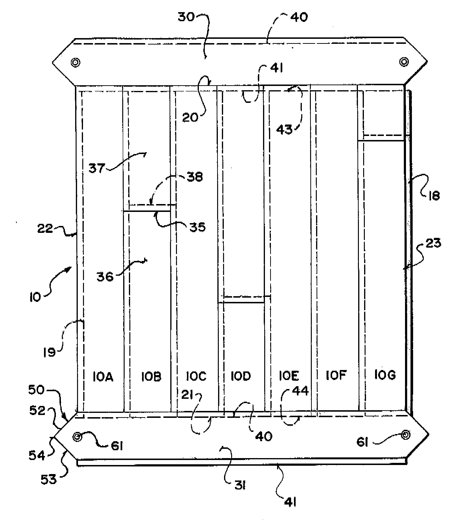
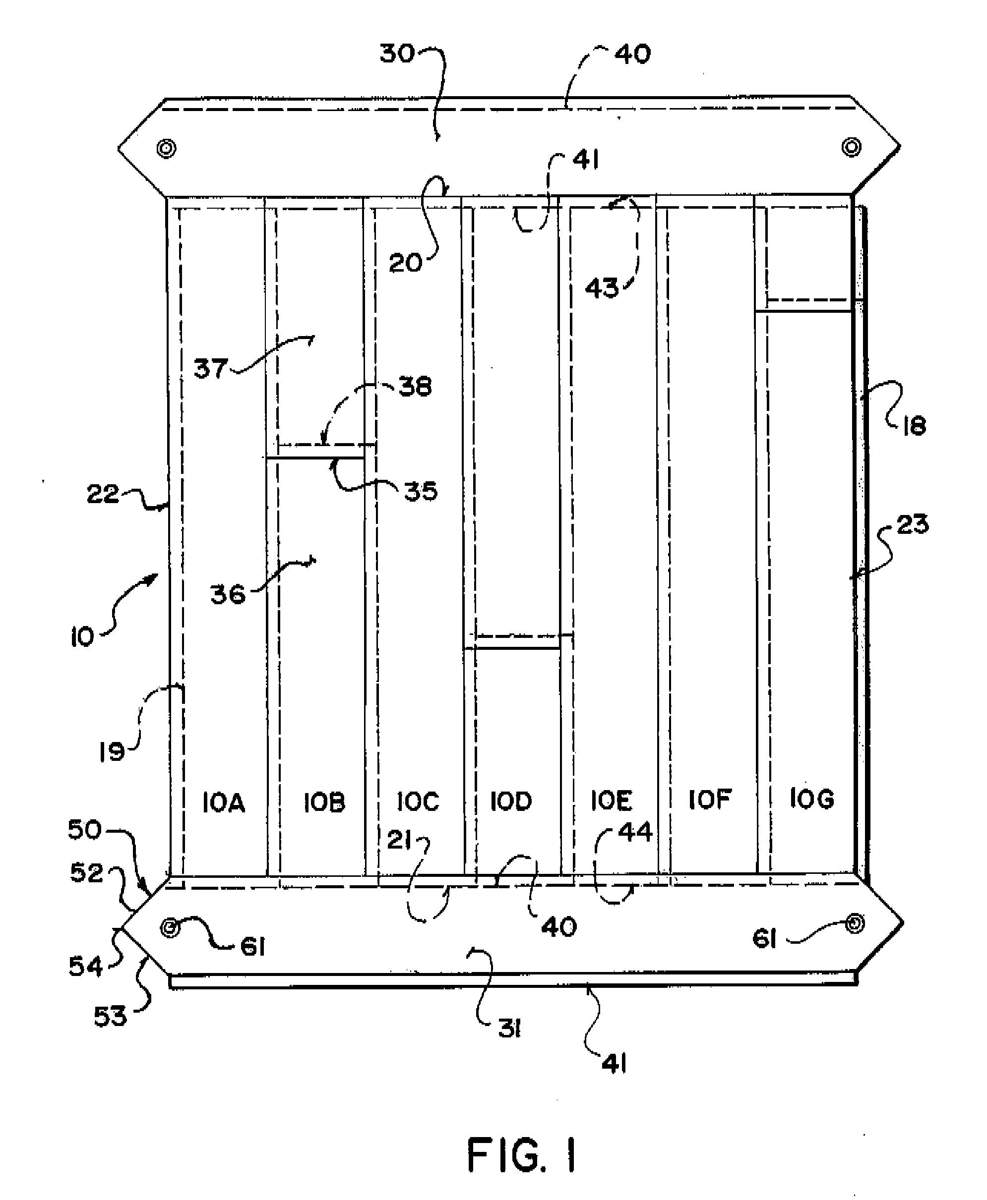
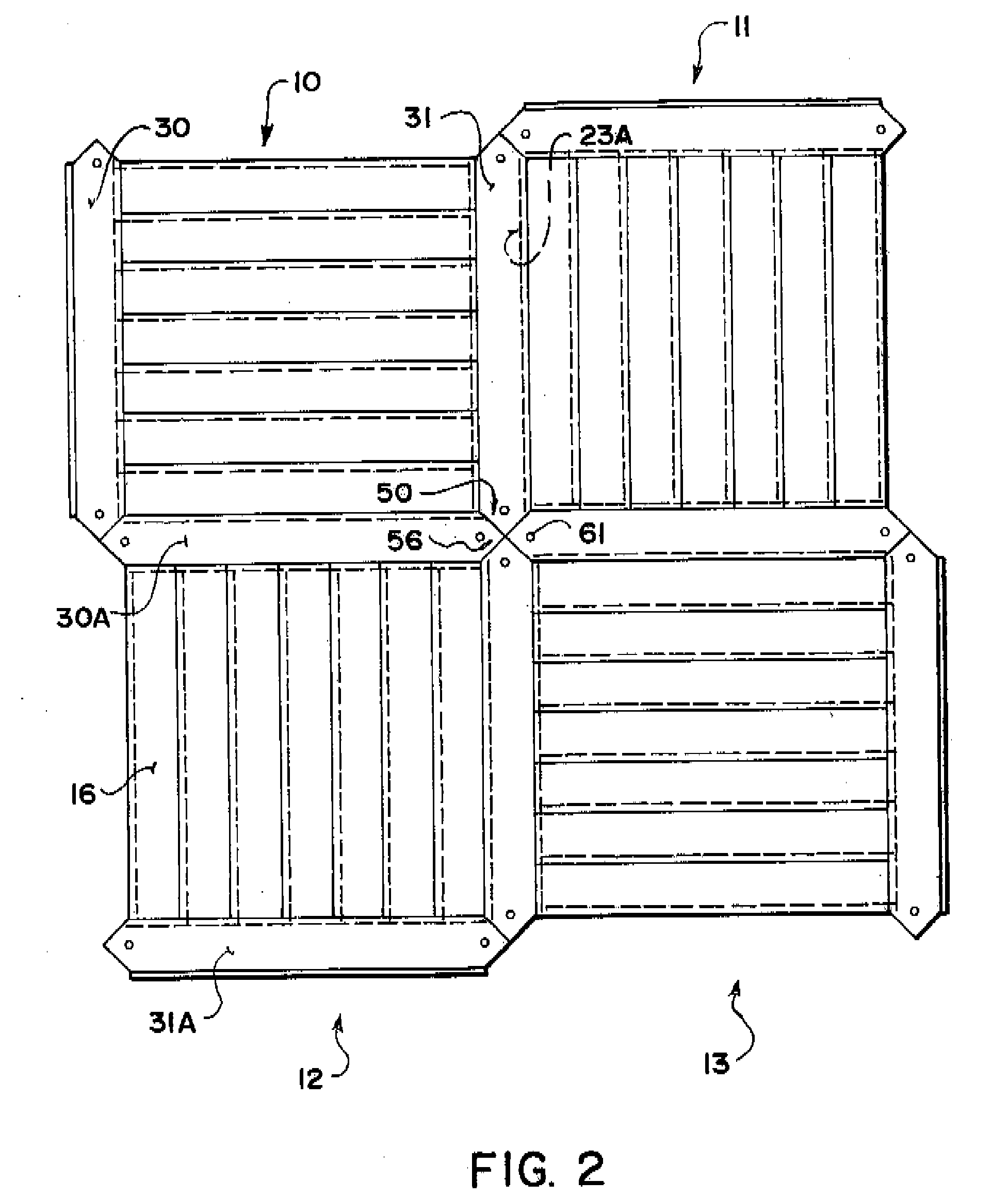
[0064]The arrangement described herein comprises a floor system defined by a series of panel members, four of which are shown at 10 through 13. Each of the panel members has a top surface 16 defining a floor surface on which the user walks and providing an attractive appearance as described hereinafter. Each of the panel members includes a bottom surface 17 for sifting on a sub floor of a conventional nature.

[0065]Each of the panel members is formed from a plurality of side by side main strips 10A to 10G which are connected together side by side to form an initial panel portion which has four side edges so that for example the panel 10 has side edges 20 and 21 which form a first pair of opposed side edges and side edges 22 and 23 which form a second pair of opposed side edges.

[...


PUM


Abstract

A panelling system preferably for floors is defined by a series of panels each formed of a plurality of tongue and groove main floor plank strips arranged side edge to side edge and cut to a common length with a tongue along one cut edge and a groove along the other. At the edges are attached first and second dividing strips formed also from the flooring planks fastened together to form a common panel member for transportation and installation. Each divider strip includes a ninety degree point extending beyond the sides of the main strips to meet with the points of other strips to fill the spaces between the panels. The strips are fastened by pins from the rear or by a bonded sheet material on the rear. A method for assembly includes re-cutting the tongue or groove along one edge after compression of the main strips together to ensure accuracy.

Description

[0001]This application is related to a co-pending application Ser. No. TO BE INSERTED (attorney docket 85518-502) filed on common date with this application which is directed to a method of forming panels of the type disclosed herein, the disclosure of which is incorporated herein by reference.[0002]This invention relates to a panelling system defined by a plurality of inter-engaging panels. The system is primarily designed for flooring but can be used for other surfaces requiring to be paneled with an attractive layer of a covering material formed in individual panels. The system is primarily designed for use with panels formed of wood but other materials can be used either to form the entire panel or a part of the panel.BACKGROUND OF THE INVENTION[0003]Various techniques have been proposed for the manufacture of wood panel flooring. Conventionally wood panel flooring is formed as tongue and groove planks which are arranged edge to edge so that the tongue of one projects into a gro...

Claims


Application Information

Patent Timeline
Patent Type & Authority Applications(United States)
IPC IPC(8): E04F15/16
CPCE04F15/16E04F2201/042E04F2201/043E04F15/02038E04F2201/07
Inventor GIBSON, KELLYHOARD, LEN
Owner GIBSON KELLY
Learn More