Hammer having shock absorbing handle

a technology of hammer and handle, which is applied in the field of striking tools, can solve the problem that none of these patents discloses a striking tool

Inactive Publication Date: 2008-12-11
HOFFMAN CHARLES J
View PDF26 Cites 11 Cited by
  • Summary
  • Abstract
  • Description
  • Claims
  • Application Information

AI Technical Summary

Problems solved by technology

However, none of these patents discloses a striking tool including a spring-action handle that would assist in absorbing some of the impact shock imparted to the user's hand, wrist, elbow, shoulder, and other portions of the body upon striking a nail, for example, and would assist in returning the hammer to its original starting position above the nail.

Method used


Image

  • Hammer having shock absorbing handle
  • Hammer having shock absorbing handle
  • Hammer having shock absorbing handle

Examples


first embodiment

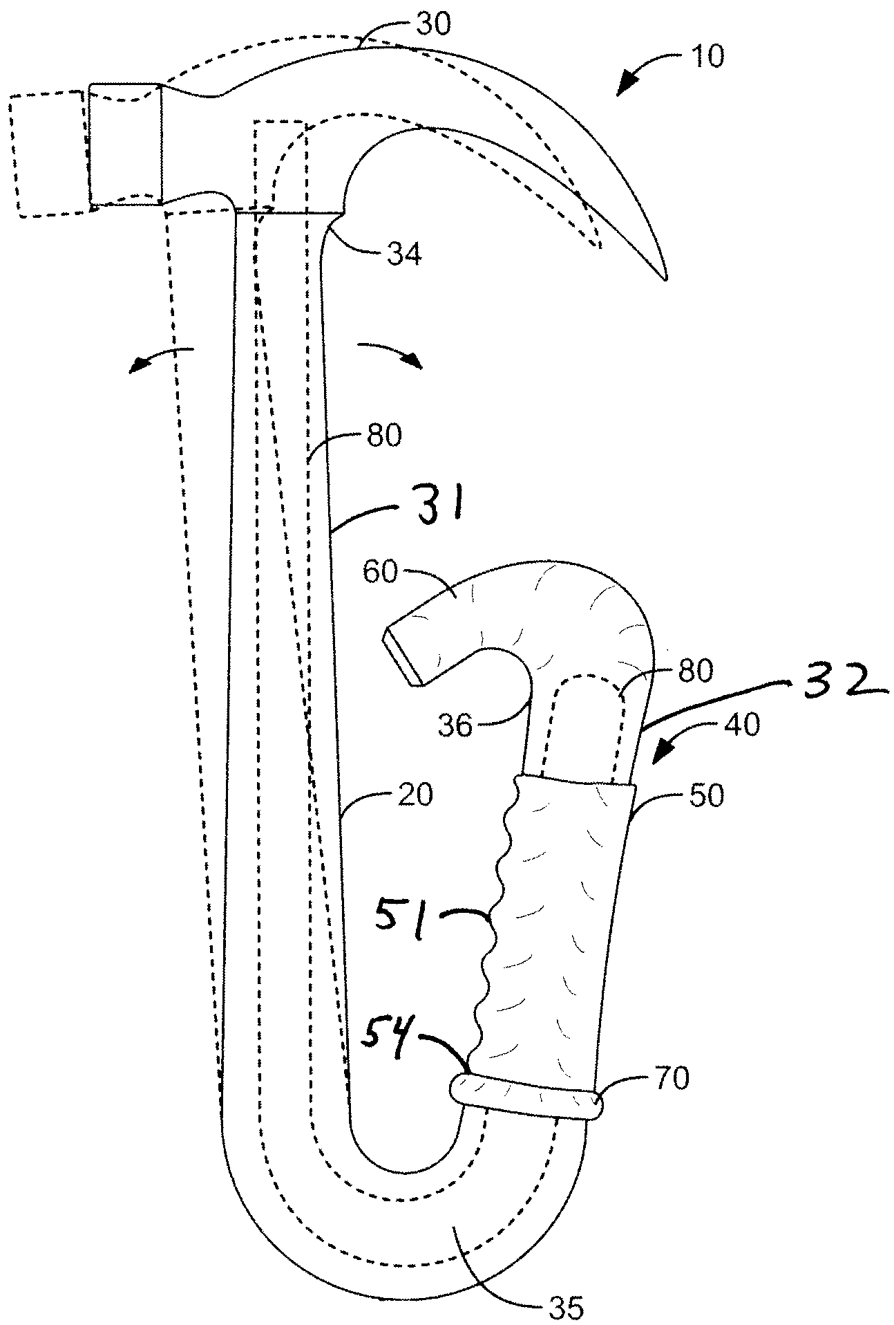
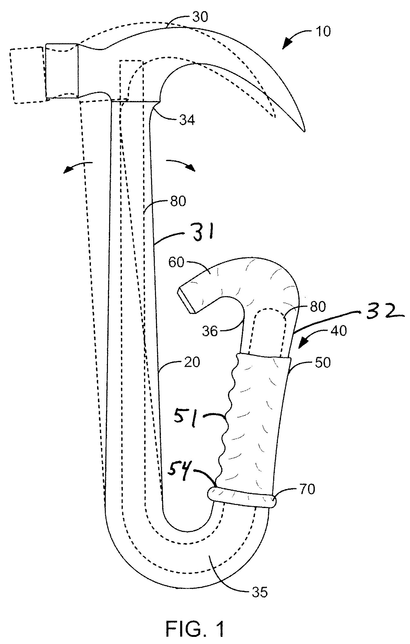
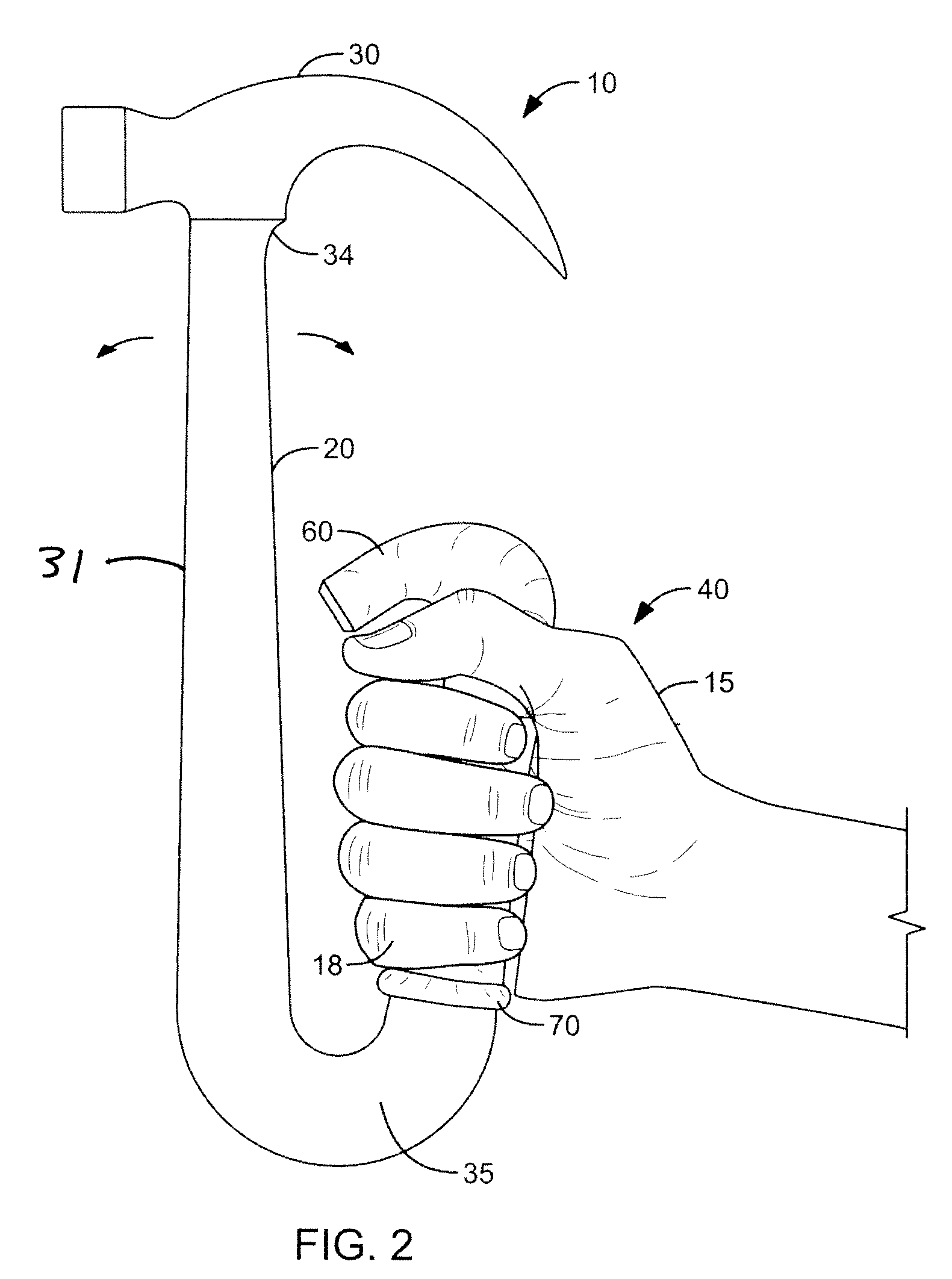
[0031]the present hammer 10 is shown in FIGS. 1-3 as comprising handle 20, having first end 34 affixed to hammer head 30. Handle 20 includes first substantially linear region 31, second substantially linear region 32, and bottom curved region 35, interposed between first linear region 31 and second linear region 32. Second linear region 32 includes gripping region 40. A hand grip 50 is disposed about a portion of linear region 32 at gripping region 40. Hand grip 50 includes finger accepting indentations 51 and lip 70 proximate lower end 54 of hand grip 50. A flange, or protrusion 60, is disposed at second end 36 of handle 20.

[0032]As shown in FIG. 1, an optional central core 80 may be disposed within handle 20. Central core 80, when present, provides additional strength and reinforcement to handle 20. Central core 80 is preferably constructed of a suitable high strength yet resilient material.

[0033]Hammer head 30 may be, for example, a conventional claw hammer head, having a strikin...

second embodiment

[0040]the present hammer 10 is shown in FIGS. 4-5. In this embodiment, first linear region 31 and second linear region 32 are again inclined away from each other at a relative acute angle of approximately seven degrees or, in an alternative embodiment, approximately ten degrees. Moreover, in this embodiment, hand grip 50 is eliminated, with the user grasping the handle surface directly at gripping region 40 of handle 20. The function of lip 70 of grip means 50 of FIGS. 1-3 is instead provided by integrally formed protrusions 70′ and 70″ on opposing sides of second linear region 32, proximate its juncture with bottom curved region 35 of handle 20. Of course, a separate hand grip, such as a hand grip rubber or rubberized material that may be substantially flush with surrounding regions of the handle, may alternatively be used. As best seen in FIG. 4, while both protrusion 70′ and 70″ have a curved apex, protrusion 70′, disposed inwardly towards first linear region 31 of handle 20, is ...


PUM


Abstract

A striking tool is disclosed that comprises a generally U-shaped or V-shaped handle constructed of a substantially resilient material and having a head fixed at one end thereof. A second end of the handle has a hand grip or gripping region adapted to be grasped by a human hand. The second end of the U-shaped or V-shaped handle includes a flange, or stop member, to inhibit the handle from slipping out of the grasping hand. The hand grip may include a lip at a lower end thereof, such that a pinky finger of the hand may be comfortably placed on either side of the lip while the hand grasps the hand grip. The resilient material construction of the handle permits a first end of the handle to flex slightly towards and away from the second end of the handle. Accordingly, during use, the striking tool provides a damped recoil and improved striking action, imparting less shock to the hand, wrist, elbow, shoulder, and other parts of the body, as compared to a conventional striking tool.

Description

CROSS-REFERENCE TO RELATED APPLICATIONS[0001]This application claims the benefit of U.S. provisional application No. 60 / 943,265, filed on Jun. 11, 2007, the entirety of which is hereby incorporated by reference.BACKGROUND OF THE INVENTION[0002]1. Field of the Invention[0003]This invention relates generally to hand tools, and more particularly to striking tools such as hammers.[0004]2. Description of Related Art[0005]Hammers and other hand tools with bent handles are known in the art. For example, U.S. Pat. No. 4,154,273 and U.S. Pat. No. 4,958,540 each teach such a device, as does Canadian Patent No. 2,208,951. Such handles may potentially provide improved control of a hammer in certain situations, and may potentially provide some strain relief to the wrist. However, none of these patents discloses a striking tool including a spring-action handle that would assist in absorbing some of the impact shock imparted to the user's hand, wrist, elbow, shoulder, and other portions of the bod...

Claims


Application Information

Patent Timeline
Patent Type & Authority Applications(United States)
IPC IPC(8): B25D1/12B25G1/01B25G1/10
CPCB25D1/045Y10T16/476B25G1/01
Inventor HOFFMAN, CHARLES J.
Owner HOFFMAN CHARLES J
Why Eureka
Try Eureka