Drive operation device of walk-behind lawn mower

a technology of drive operation and drive lever, which is applied in the direction of mowers, agriculture tools and machines, agriculture, etc., can solve the problems of temporary reduction of the speed of the machine in a typical case, further difficulty in operation of the throttle lever, etc., and achieve and the control of the travel speed of the machine

Inactive Publication Date: 2007-11-08
KYOEISHA
View PDF23 Cites 10 Cited by
  • Summary
  • Abstract
  • Description
  • Claims
  • Application Information

AI Technical Summary

Benefits of technology

[0012]According to the second aspect of the invention, since drive operation can be performed with grasping the three components of the handle, clutch lever, and throttle lever together, control of engine rotation frequency, that is, control of travel speed of the machine, in addition, on / off operation of a clutch can be performed by a hand grasping the handle. Accordingly, since each operation of start and stop of travel of the machine can be performed by grasping the clutch lever by a hand grasping the handle, or simply releasing the clutch lever grasped together with the handle by the hand, not only control operation of travel speed of the machine by the throttle lever, but also each operation of start and stop of travel of the machine is facilitated. Moreover, since the throttle lever is provided in the obliquely lower front of the handle, travel speed of the machine can be controlled by lightly drawing or separating the lever with respect to the handle by fingertips of the hand grasping the handle, thereby travel speed of the machine can be controlled.
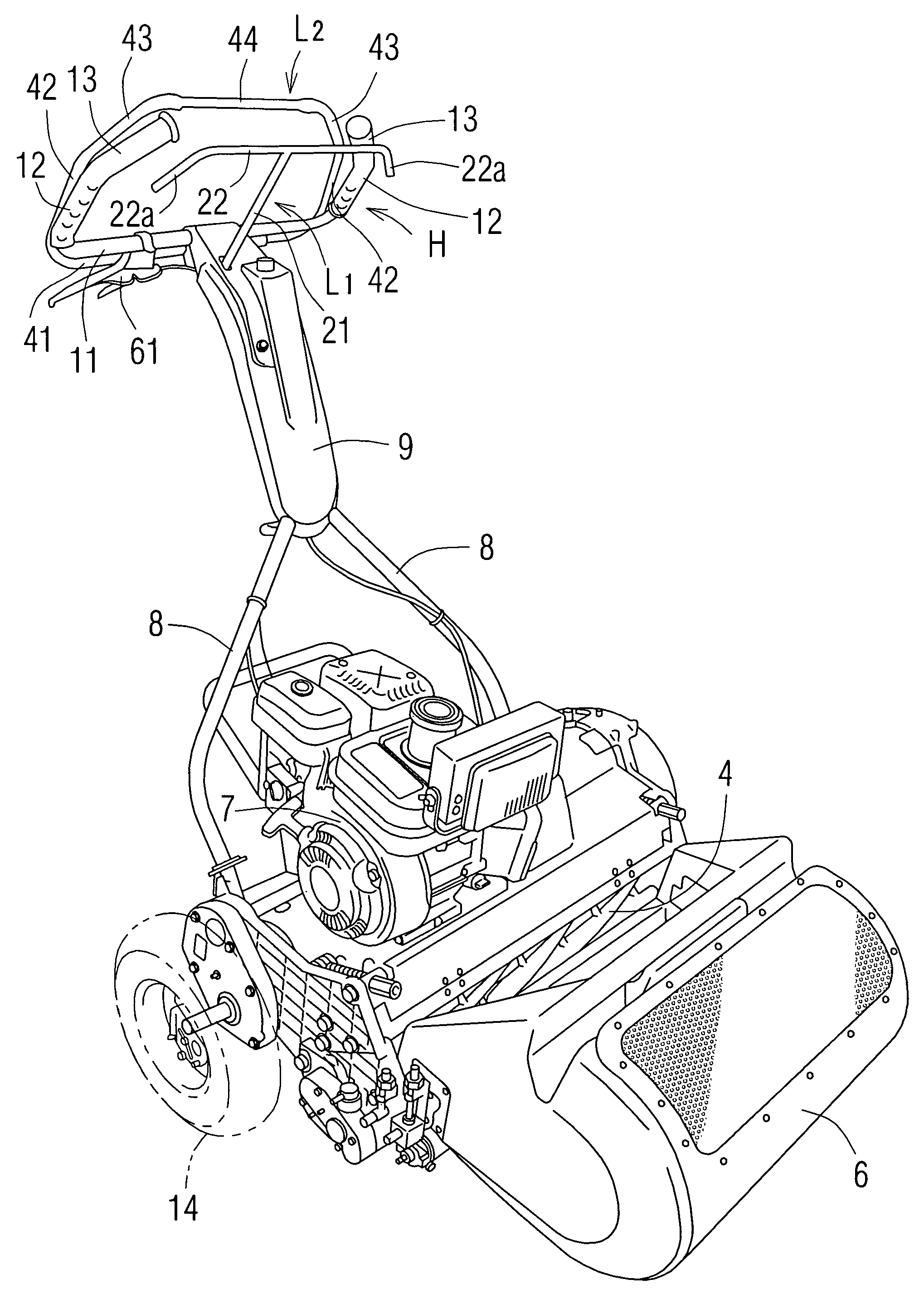
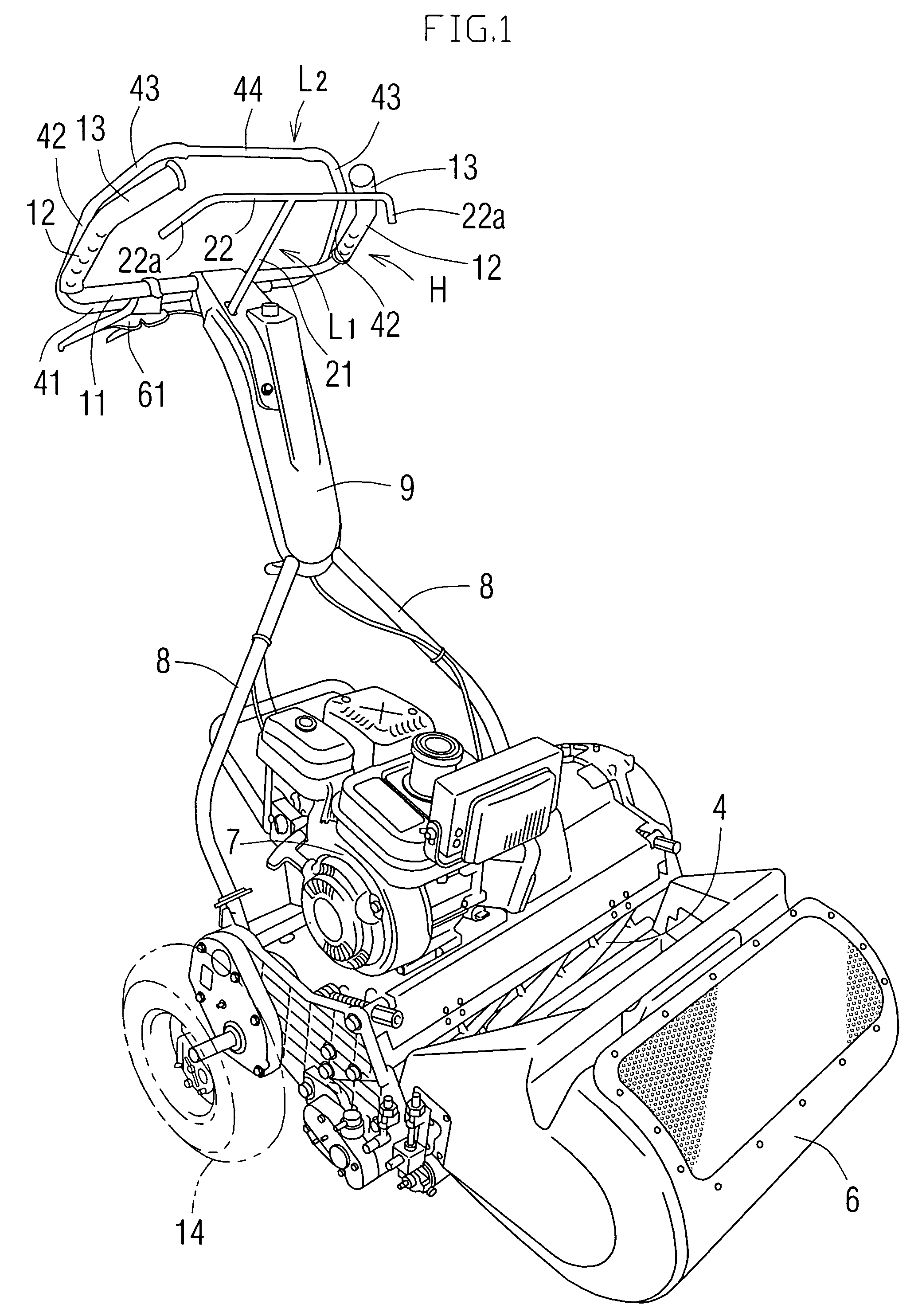
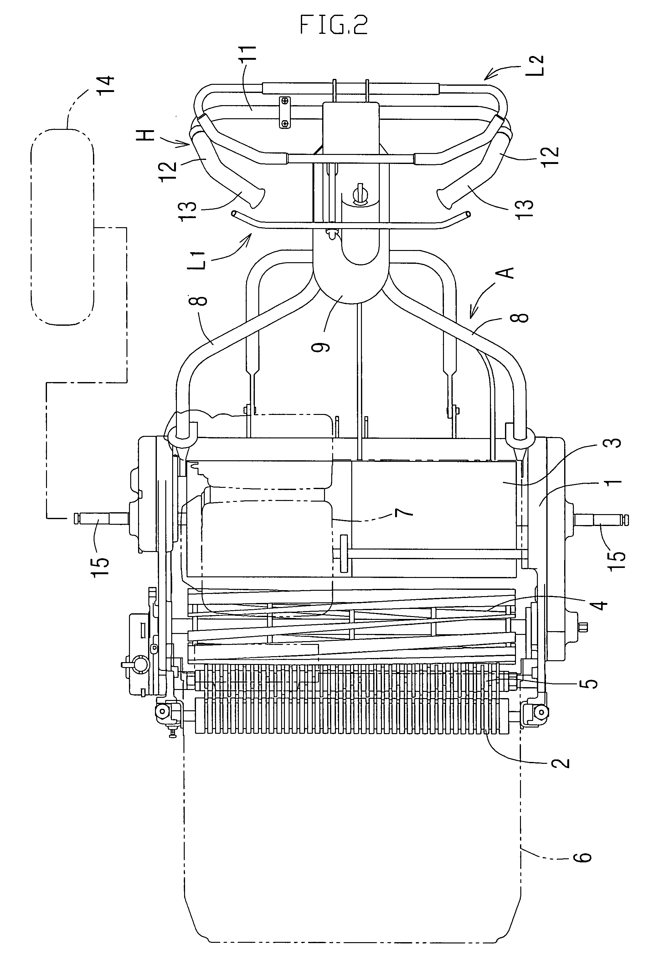
[0013]A third aspect of the invention is characterized in that in the second aspect of the present invention, the handle is in a shape in which both ends of a horizontal fixing portion fixed to the handle arm is inwardly bent at an angle of more than 90 degrees, thereby a horizontal pair of grasp portions being oppositely disposed are formed in a standing manner; the throttle lever is in an approximately T-shape, in which a horizontal rod portion is provided along a lateral direction of the machine in upper ends of rotation support rods rotatably supported in a condition standing from the handle arm; and both ends of the horizontal rods of the throttle lever are bent to an oblique lower side such that they are approximately parallel to the grasp portions in a condition of being disposed in an overlapped manner with the grasp portions along the lateral direction of the machine so that they are easily grasped by the hands grasping the grasp portions of the handle, thereby both the ends are formed as drawing portions.
[0014]According to the third aspect of the invention, since the grasp portions of the loop handle and the drawing portions of the throttle lever are disposed approximately parallel to each other in the overlapped manner along the lateral direction of the machine, the drawing portions of the throttle lever can be lightly drawn by fingertips of hands grasping the grasp portions of the handle. Therefore, particularly when the machine is turned, a condition that the throttle lever is drawn by an optimum amount by fingertips of one of the hands grasping the grasp portions of the handle can be kept, consequently drive operation is facilitated when the machine is turned.
[0015]A forth aspect of the invention is characterized in that in any one of the first to third aspects of the invention, the throttle lever is rotationally biased in a direction to be separated from the handle, and the throttle lever is drawn to a handle side to be close to the handle, thereby engine rotation frequency is increased, and the engine rotation frequency is minimized by releasing the throttle lever.
[0016]According to the forth aspect of the invention, when the throttle lever being drawn to the handle by hands grasping the handle is released, the throttle lever is maximally separated from the handle by rotation biasing force so that the engine rotation frequency is minimized, and the clutch is made to be off at the same time, thereby the machine is stopped. Accordingly, even if the throttle lever is not rotated in each case by a hand released from the handle unlike a usual machine, the machine can be momentarily stopped, or can start travelling, consequently drive operation associated with stop of the machine and start of travel is facilitated.
[0017]In this way, in an embodiment of the invention, since the throttle lever can be drawn by either of hands grasping the loop handle, an operator can draw the throttle lever by one or both of hand grasping the handle, and can control the engine rotation frequency by controlling the amount of drawing. Therefore, when travel speed is desired to be controlled during lawn mowing, the amount of drawing of the throttle lever can be controlled in a posture with the handle being grasped by hands without releasing hands from the handle, and when the machine is turned, since the throttle lever can be drawn by either of hands, the throttle lever is drawn by the necessary amount by one of hands grasping the handle, thereby the machine can be turned at optimum speed in the same drive operation posture except for difference in horizontal direction in a turn in either of right and left directions, consequently drive operation is facilitated when the machine is turned.

Problems solved by technology

Accordingly, there has been a difficulty that when the machine is turned, speed of the machine is temporarily reduced in a typical case, therefore the throttle lever is complicatedly operated in the above way, and since the throttle lever is provided at only one side in a lateral direction of the handle arm, when lawn is mowed with the machine being alternately turned in directions opposite to each other, the throttle lever is in a position far from an operator side in either turn, consequently the throttle lever is further hard to be operated.

Method used


Image

  • Drive operation device of walk-behind lawn mower
  • Drive operation device of walk-behind lawn mower
  • Drive operation device of walk-behind lawn mower

Examples


Embodiment Construction

[0028]First, an outline of a walk-behind lawn mower is described with reference to FIGS. 1 to 3, and then a drive operation device according to an embodiment of the invention is described. FIG. 1 is an overall perspective view of a walk-behind lawn mower according to an embodiment of the invention; FIG. 2 is a plane view of the lawn mower in a condition that a grass catcher 6 is removed; and FIG. 3 is a side view of the lawn mower in a condition of lawn mowing. In the lawn mower, a front roller 2 and a drum 3 are mounted with a predetermined interval in the front and the rear of a machine 1 respectively, a reel cutter 4 is arranged between the front roller 2 and the drum 3, and a thatching roller 5 for raking dried grass and the like biting in lawn before mowing is arranged between the reel cutter 4 and the front roller 2. Mowing height of lawn is determined by controlling height of the front roller 2 with respect to the machine 1. The grass catcher 6 for gathering and accommodating...


PUM


Abstract

A walk-behind lawn mower in a form that a handle arm is integrally provided toward an obliquely upper back in a rear of a machine, and a loop handle is provided at a rear end of the relevant handle arm with slightly tilting forward, and a driver performs drive operation while walking following the machine that travels by itself at a back of the machine, includes a throttle lever, the throttle lever being able to be drawn together with the handle by being operated by either of right and left hands grasping the handle, in addition, engine rotation frequency being able to be controlled using the amount of drawing, wherein the throttle lever is rotatably provided on the handle arm in an obliquely lower front or obliquely upper back of the handle.

Description

BACKGROUND OF THE INVENTION[0001]1. Field of the Invention[0002]The present invention relates to a drive operation device of a walk-behind lawn mower in which a loop handle is provided, and an operator performs drive operation while walking following a machine that travels by itself at a back of the machine.[0003]2. Description of Related Art[0004]In the walk-behind lawn mower in the above form (hereinafter, simply abbreviated as “lawn mower” in some cases), a handle arm is integrally provided toward an obliquely upper back in a rear of a machine, and a loop handle is provided at a rear end of the relevant handle arm with slightly tilting forward, and an operator performs drive operation while walking following the machine that travels by itself at a back of the machine with grasping respective standing portions at both sides of the handle with both hands.[0005]In the lawn mower in the above form, a lawn mower is known, which is in a configuration where a clutch lever is provided ne...

Claims


Application Information

Patent Timeline
Patent Type & Authority Applications(United States)
IPC IPC(8): A01D75/28
CPCA01D34/824
Inventor HIBI, YOSHIHISAPARRIS, GRAEME SIDNEYHAYASHI, AKIO
Owner KYOEISHA
Why Eureka
Try Eureka