Solar Collector

a solar collector and solar energy technology, applied in the field of solar collectors, can solve the problems of rapid decline in the efficiency of conventional collectors, and achieve the effects of reducing the cost of installation

Inactive Publication Date: 2008-12-11
JONES DARRYL JOHN +1
View PDF2 Cites 10 Cited by
  • Summary
  • Abstract
  • Description
  • Claims
  • Application Information

AI Technical Summary

Benefits of technology

[0064]Now that a preferred embodiment of the present invention has been described in some detail it will be apparent to those skilled in the art that the solar collector, the solar powered heat exchanger, or the solar tracking apparatus have the following advantages:
[0065]1. the solar collector, having a sealed collector housing within which at least a partial vacuum can be drawn, provides efficient absorption of solar energy for heating of the heat transfer fluid and allows higher temperatures to be achieved;
[0066]2. the configuration of the solar collector and orientation of its inlet and outlet provides an effective flow of the heat transfer fluid promoted by a thermosiphon effect at the inlet of the collector tank;
[0067]3. the solar powered heat exchanger utilises density differences in the heat transfer fluid between the bottom of the collector (cooler and higher density) and the top of the heat exchanger (hotter and lower density) wherein the heat transfer fluid heated in the collector becomes less dense and rises by natural convection forces to the highest point of the heat exchange system whereas as the fluid cools in the heat exchanger it becomes more dense and falls to the bottom of the system; and
[0068]4. the solar tracking apparatus is effective in tracking the sun daily and / or seasonally to preferably provide maximum sunlight exposure for the solar collector.

Problems solved by technology

Because of this effect, efficiency of conventional collectors declines rapidly as the temperature of the heated fluid rises until eventually the long wave radiation losses from the collector surface equal the short wave radiation being absorbed by the collector and no further heating can occur.

Method used


Image

  • Solar Collector
  • Solar Collector
  • Solar Collector

Examples


Embodiment Construction

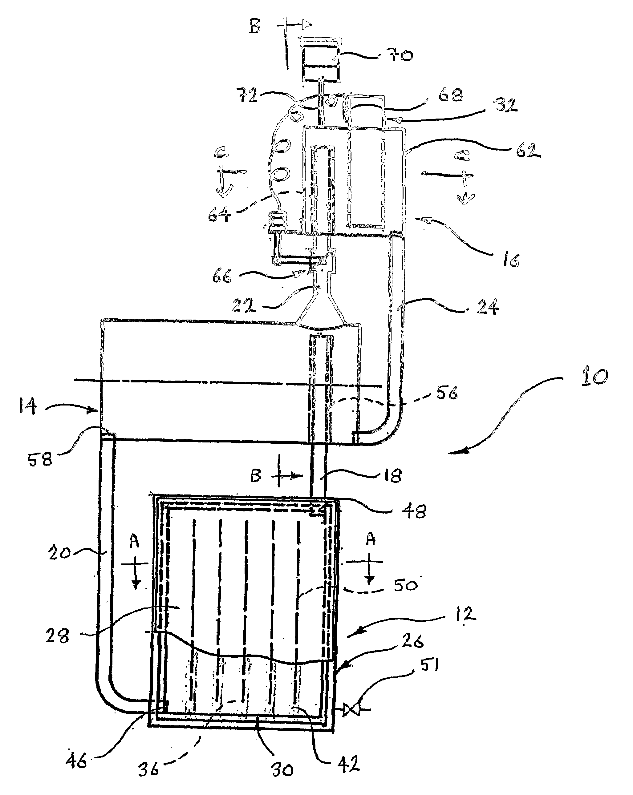
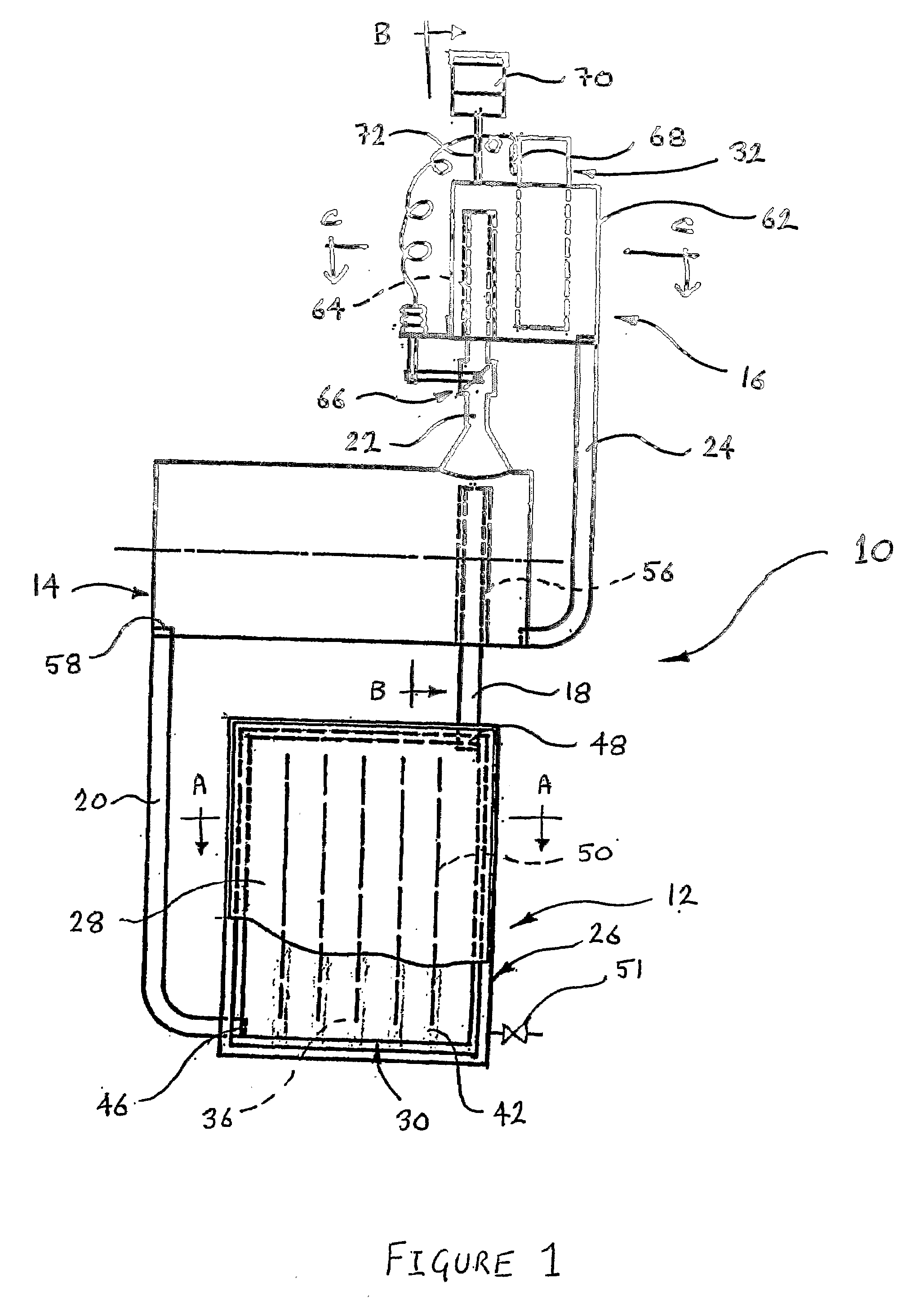
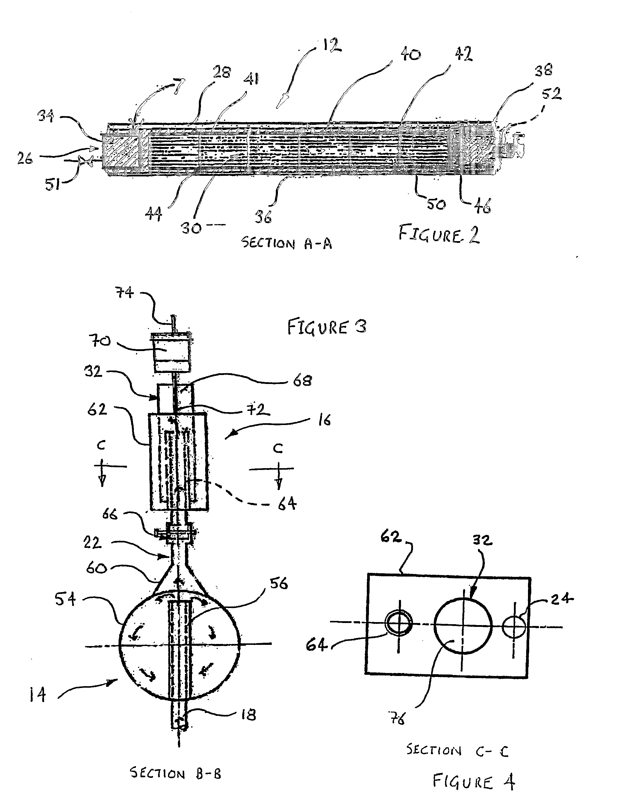
[0029]As shown in FIG. 1 there is a solar powered heat exchanger designated generally as 10 comprising a solar collector 12, a heat accumulator 14, and a heat exchanger 16. The solar collector 12 is operatively coupled to the heat accumulator 14 via a supply line 18 and a recirculation line 20. The heat accumulator 14 is in turn operatively coupled to the heat exchanger 16 via a feed line 22 and a return line 24.

[0030]The solar collector 12 includes a collector housing 26 having a translucent or transparent surface in the form of a glass pane 28. The solar collector 12 also includes a collector tank 30 located within the collector housing 26 and in operation being adapted to contain a heat transfer fluid such as glycol or a water / glycol mixture. The water / glycol mixture is heated by the solar collector 12 and circulates by a thermosiphon effect between the solar collector 12 and the heat accumulator 14 via the supply and the recirculation lines 18 and 20, respectively. The solar hea...


PUM


Abstract

The invention is a solar powered heat exchanger (10) comprising a solar collector (12), a heat accumulator (14), and a heat exchanger (16). The solar collector is operatively coupled to the heat accumulator (14) via a supply line (18) and a recirculation line (20). The heat accumulator (14) is in turn operatively coupled to the heat exchanger (16) via a feed line (22) and a return line (24).

Description

FIELD OF THE INVENTION[0001]The present invention relates broadly to a solar collector and a solar powered heat exchanger. The invention also relates to a solar tracking apparatus and a combination solar collector / tracking apparatus.BACKGROUND OF THE INVENTION[0002]Solar hot water systems of a conventional construction include a solar collector connected to a storage cylinder containing stored water. The solar collector is fabricated from an arrangement of heat absorbing pipes or tubes layed out in a parallel or serpentine arrangement. In one form the tubes are formed in a black heat absorbing mat which can be placed on a rooftop to capture the sunlight. In another form the pipes are housed within an enclosure having a glass pane front which is exposed to sunlight and the efficiency of heating is improved under the influence of the greenhouse effect. The system may provide direct heating where the stored water itself is circulated through the solar collector. Alternatively, indirect...

Claims


Application Information

Patent Timeline
Patent Type & Authority Applications(United States)
IPC IPC(8): F24J2/38F24J2/05F24S50/20F24S10/40
CPCF24J2/05F24J2/345F24J2/38F24J2/44F24J2/523F24J2/5424Y02E10/44Y02E10/47F24S30/455F24S60/30F24S50/20F24S25/10F24S90/10F24S10/40
Inventor JONES, DARRYL JOHNCOLLINS, GRAEME ALLAN
Owner JONES DARRYL JOHN
Why Eureka
Try Eureka