Vessel, Heating Apparatus and Method of Heating a Feedstock

a heating apparatus and feedstock technology, applied in the direction of heating apparatus, lighting and heating apparatus, furnace types, etc., can solve the problem that the efficiency of heating a feedstock inside the known vessel using emr is less than it might otherwise b

Inactive Publication Date: 2008-12-11
ENERGY ENVIRONMENTAL
View PDF59 Cites 15 Cited by
  • Summary
  • Abstract
  • Description
  • Claims
  • Application Information

AI Technical Summary

Benefits of technology

[0076]This is useful where the composition of the gases released from the feedstock changes as the feedstock progresses along the vessel, because it enables the gases released from the feedstock to be separated by composition.
[0077]For example, in the case of oily cuttings cleaning (oily cuttings are a by-product of oil drilling) when the oily cuttings are heated, first steam is released as water in the cuttings is evaporated then oil vapour is released as the oil in the cuttings is evaporated. By p

Problems solved by technology

Heating a feedstock inside the known vessel using EMR is therefore less efficient than it might otherwise be, bec

Method used


Image

  • Vessel, Heating Apparatus and Method of Heating a Feedstock
  • Vessel, Heating Apparatus and Method of Heating a Feedstock
  • Vessel, Heating Apparatus and Method of Heating a Feedstock

Examples


Embodiment Construction

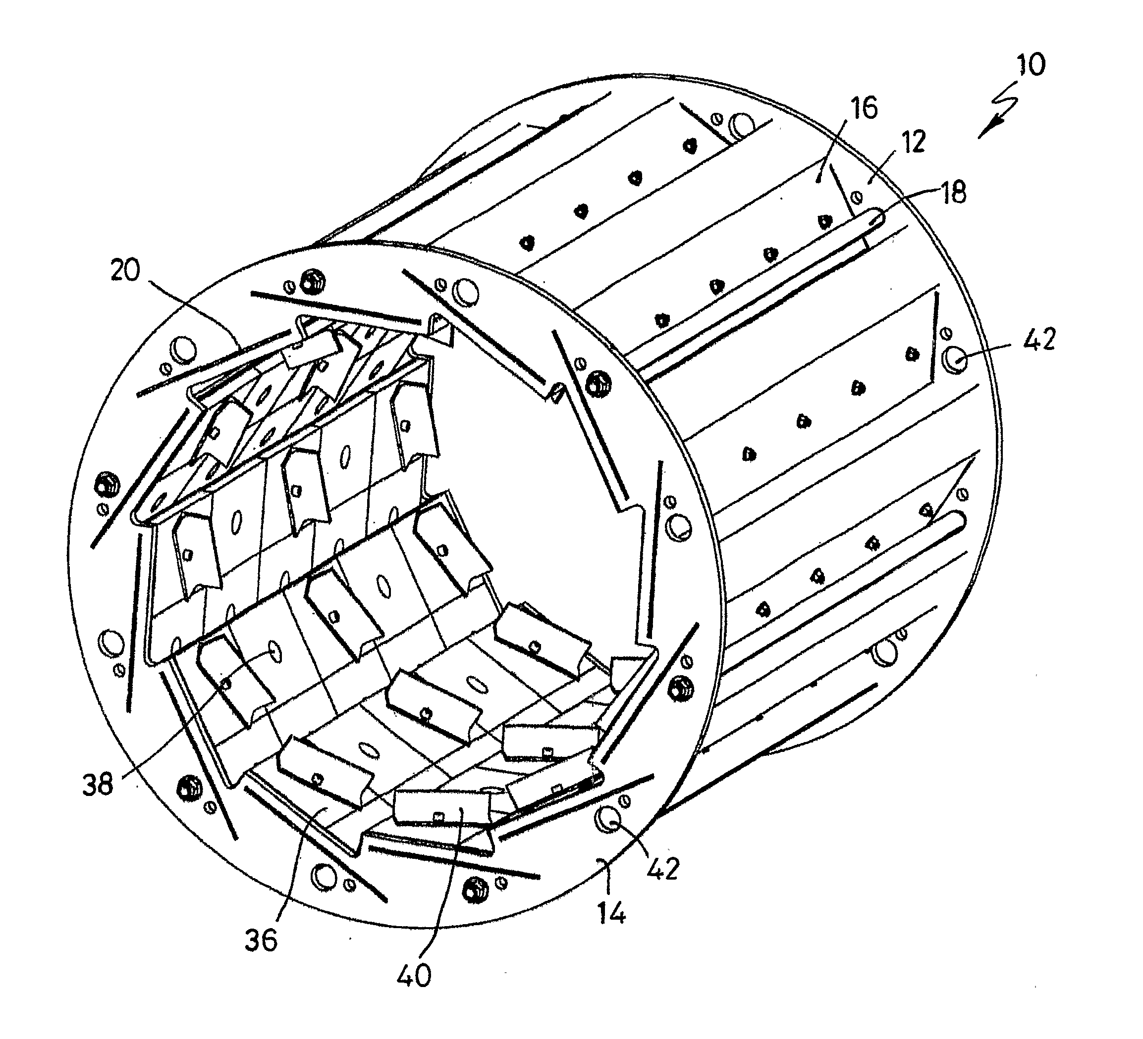
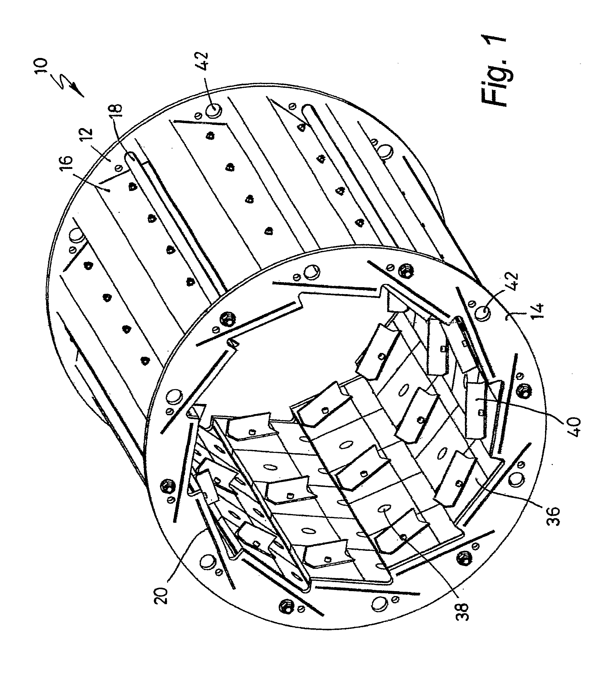
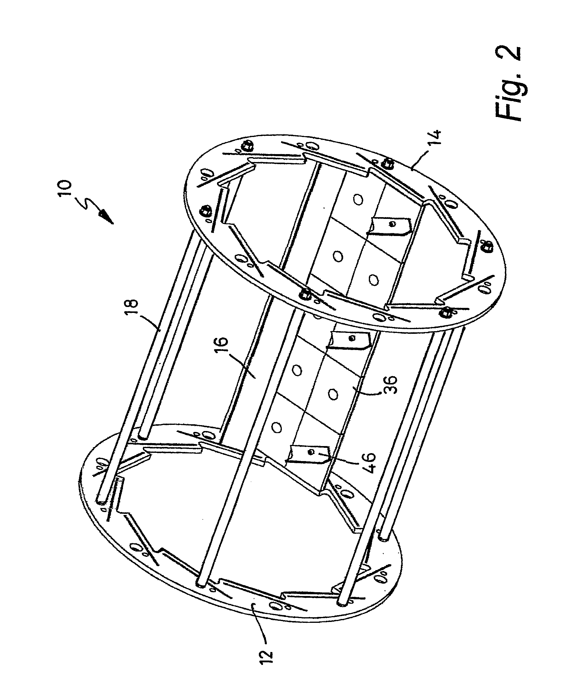
[0108]The vessel 10 of FIG. 1 comprises first and second end walls 12 and 14, and twelve slats 16 secured between the end walls 12 and 14 by six tie rods 18 so as to form a side wall of the vessel. The ends of each slat 16 are formed with tabs that engage with slots 20 in the end walls 12 and 14.

[0109]Turning briefly to FIGS. 3a, 3b and 3c, each slat 16 consists of a wide flat portion 22 at the ends of which the tabs 24 are formed, and right-angled lip portion 26 which extends from one edge of the wide flat portion 22. The portions 22 and 26 are formed with a large number of 4 mm diameter circular holes 28 with a pitch of 6.5 mm between the centres of adjacent holes. The portion 22 has 10 larger diameter bolt holes 29 arranged in two lines of five holes.

[0110]The slats 16 are secured between the end walls 12 and 14 such that a slot of approximately 1 mm width is formed between an outer surface 30 of the wide flat portion 22 of each slat 16 and the edge 32 of the lip portion 26 of a ...


PUM


Abstract

A vessel (10) for a feedstock that is to be heated using radio frequency electromagnetic radiation (EMR), the vessel being adapted for rotation about an axis that passes through the vessel and having an inlet aperture through which the feedstock may be introduced into the vessel and a wall (16) for retaining the feedstock in the vessel, wherein the wall (16) has at least one vent for venting gases released by the feedstock, the at least one vent being so formed that rotation of the vessel about the axis prevents the feedstock from entering the vent, thereby retaining the feedstock in the vessel. Also heating apparatus (50) comprising such a vessel (10), means (54) for introducing a feedstock into the vessel, means (56, 62, 64, 66) for discharging the feedstock from the vessel, a source (58, 80) of EMR and drive means (75, 200, 202) operable to rotate the vessel (10) about an axis that passes through the vessel. Also a method of heating a feedstock using EMR, comprising the steps of delivering a feedstock into such a vessel, directing EMR at and/or introducing EMR into the vessel and rotating the vessel so as to tumble the feedstock.

Description

FIELD OF THE INVENTION[0001]This invention relates to a vessel for a feedstock that is to be heated using radio frequency electromagnetic radiation (EMR), to heating apparatus that includes such a vessel and to a method of heating a feedstock using such a vessel.BACKGROUND TO THE INVENTION[0002]It is well known to heat a feedstock using radio frequency electromagnetic radiation (EMR).[0003]A known vessel for a feedstock that is to be heated using EMR consists of a tube that is substantially transparent to EMR, such that EMR directed at the tube passes through a wall of the tube into the feedstock inside the tube.[0004]Heating of the feedstock by the EMR causes gases to be released from the feedstock, which gases must be extracted from the ends of the tube. Until the gases are extracted from the ends of the tube, they absorb a portion of the EMR directed at the tube, which portion of the EMR is prevented from reaching the feedstock. Heating a feedstock inside the known vessel using E...

Claims


Application Information

Patent Timeline
IPC IPC(8): H05B6/64F26B3/30F26B3/347F26B11/18F26B21/14H05B6/78H05B6/80
CPCF26B3/30F26B3/347F26B11/181F26B21/14H05B6/78H05B6/784F27B7/08H05B6/80F27B7/162F27B7/12
Inventor ERSKINE, WILLIAM ROBERTSON CUNNINGHAMREVELL, ANTHONY
Owner ENERGY ENVIRONMENTAL
Why Eureka
Try Eureka