Light emitting device, area light source apparatus and image display apparatus

Active Publication Date: 2008-12-11
SATURN LICENSING LLC
View PDF17 Cites 81 Cited by
  • Summary
  • Abstract
  • Description
  • Claims
  • Application Information

AI Technical Summary

Benefits of technology

[0019]With the light emitting apparatus, the amount of light which goes out laterally with respect to the optical axis from within the light emitted from the light emitting diode is great. Consequently, uniformity of the luminance can be assured.
[0020]Preferably, the lens and the sealing resin member define therebetween an air layer through which the light emitted from the light emitting diode passes. With the light emitting device, the light is refracted at the boundary surface between the sealing resin member and the air layer and at the boundary surface between the air layer and the lens so as to be directed laterally. Therefore, the amount of light to go out laterally can be increased.
[0021]Preferably, the light emitting device further include a transparent coupling layer provided between the lens and the sealing resin member for c

Problems solved by technology

Accordingly, there is the possibility that unevenness of luminance on the display panel may be caused

Method used


Image

  • Light emitting device, area light source apparatus and image display apparatus
  • Light emitting device, area light source apparatus and image display apparatus
  • Light emitting device, area light source apparatus and image display apparatus

Examples


Example

[0045]In the following, a light emitting device, an area light source apparatus and an image display apparatus according to a preferred embodiment of the present invention are described with reference to the accompanying drawings.

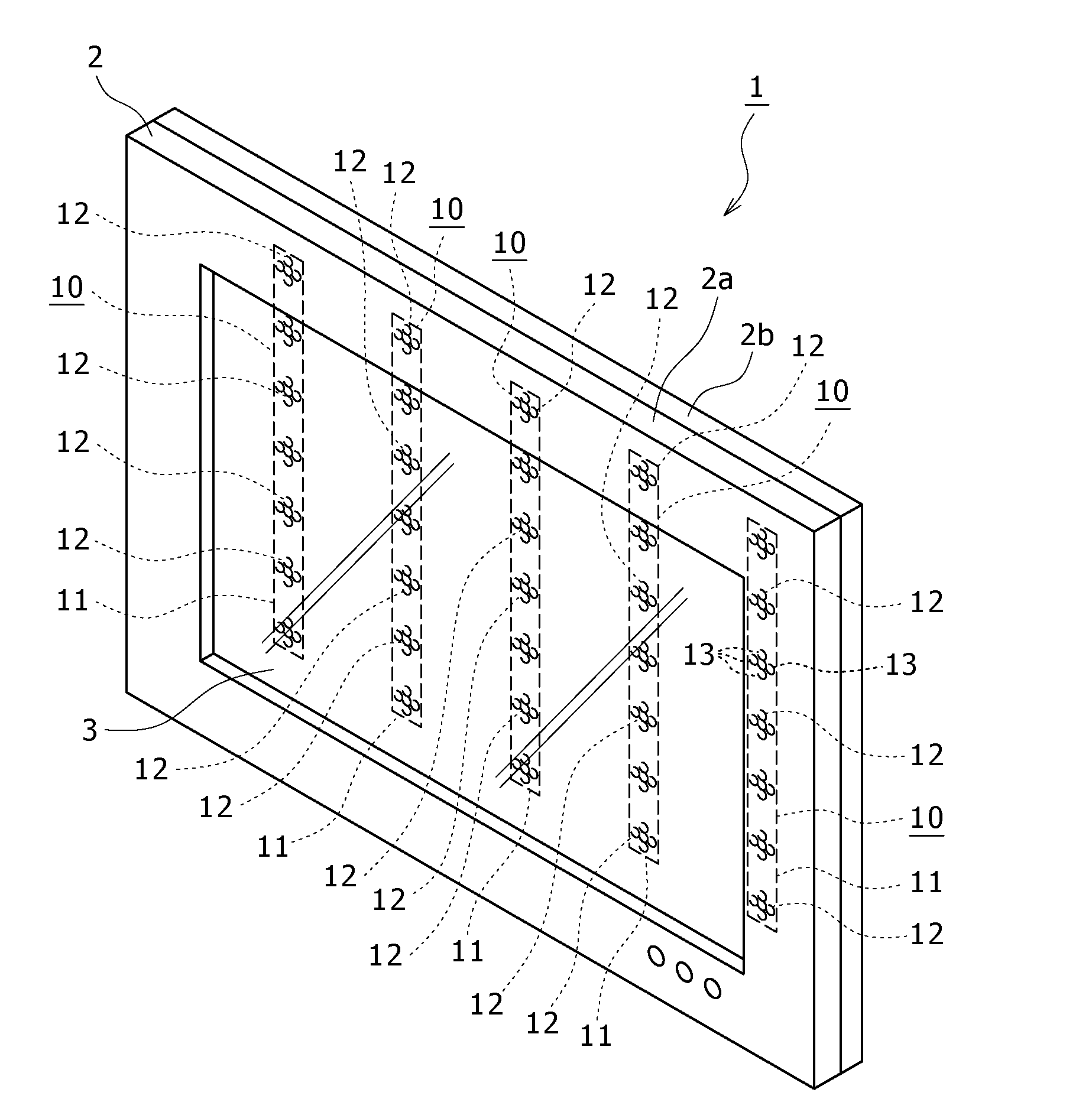
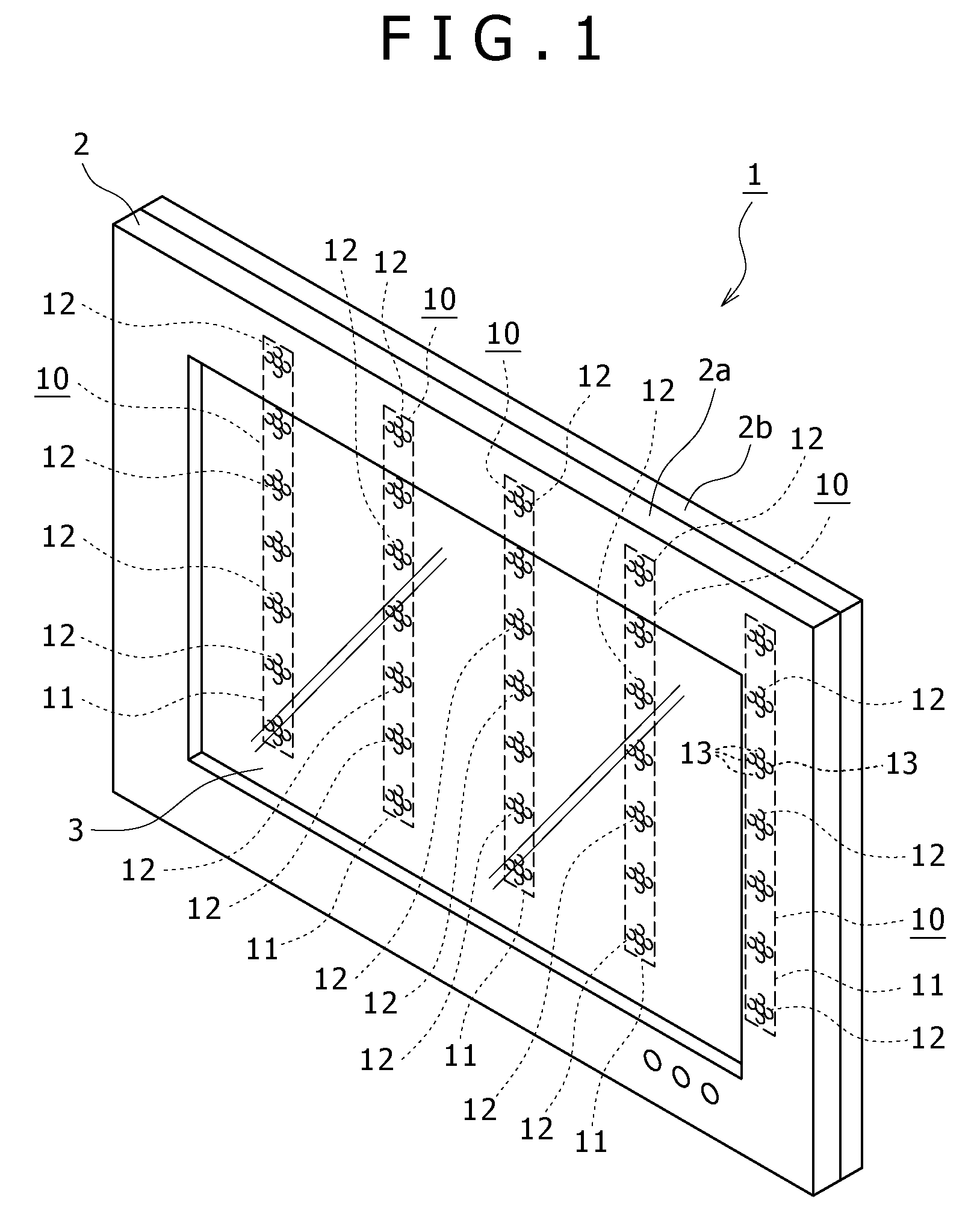
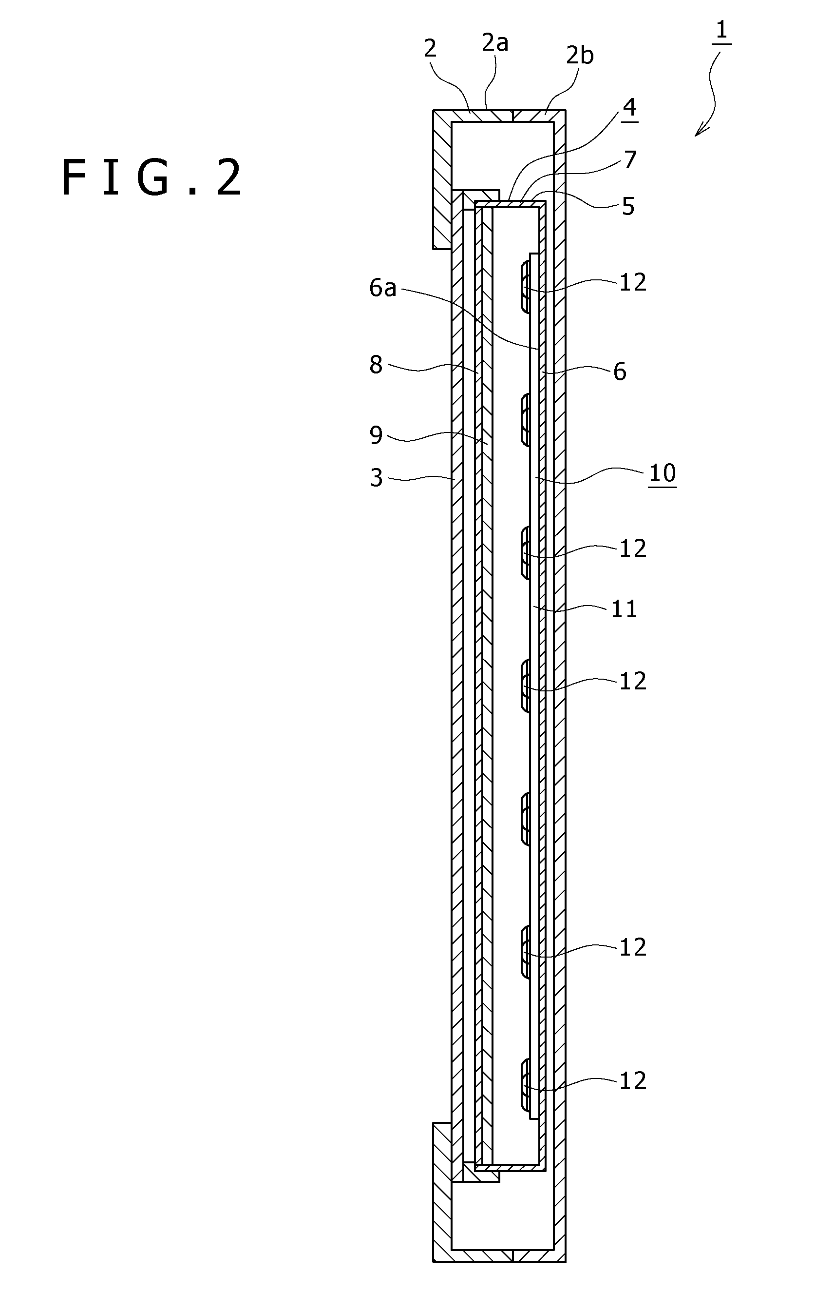
[0046]In the preferred embodiment of the present invention described below, the image display apparatus according to an embodiment of the present invention is applied to a television receiver for displaying an image on a liquid crystal panel. Further, the area light source apparatus according to another embodiment of the present invention is applied to an area light source apparatus used in the television receiver, and the light emitting device according to a further embodiment of the present invention is applied to a light emitting device used in the area light source apparatus.

[0047]It is to be noted that the application of the present invention is not limited to any of a television receiver having a liquid crystal panel and an area light source apparatus...


PUM


Abstract

Disclosed herein is a light emitting device, including: a light emitting diode; an sealing resin member having an arrangement face and configured to seal the light emitting diode; and a lens disposed on the arrangement face of the sealing resin member and formed so as to have a circular shape as viewed in the direction of an optical axis of light emitted from the light emitting diode, the lens having a concave portion formed at a central portion in such a manner as to be concave toward the sealing resin member.

Description

CROSS REFERENCES TO RELATED APPLICATIONS[0001]The present invention contains subject matter related to Japanese Patent Application JP 2007-150823 filed in the Japan Patent Office on Jun. 6, 2007, the entire contents of which being incorporated herein by reference.BACKGROUND OF THE INVENTION[0002]1. Field of the Invention[0003]This invention relates to a light emitting device, an area light source apparatus and an image display apparatus.[0004]2. Description of the Related Art[0005]An illumination apparatus is available which illuminates using a plurality of light emitting devices each having a light emitting diode as a light source.[0006]An illumination apparatus of the type described is used, for example, as an illuminator wherein the light source is utilized for direct illumination or is used in an image display apparatus such as a television receiver wherein the light source is used for backlight illumination.[0007]In an image display apparatus such as a television receiver, a pl...

Claims


Application Information

Patent Timeline
IPC IPC(8): G09G3/32F21V14/00F21V11/00F21V5/00H01L33/58H01L33/56
CPCF21V5/04F21V7/0091F21V13/04F21W2131/103F21Y2101/02G02B6/003G02F1/133603H01L33/54H01L33/58G02B19/0028G02B19/0061F21Y2115/10G02F1/133607
Inventor OHKAWA, SHINGOOKU, TAKASHINAKAKI, KENICHISHIBANUMA, TETSUO
Owner SATURN LICENSING LLC
Why Eureka
Try Eureka