

Ink jet cartridge
- Summary
- Abstract
- Description
- Claims
- Application Information
AI Technical Summary
Benefits of technology
Problems solved by technology
Method used
Image

Examples
first embodiment
[0039]A first embodiment of the present invention will be described below with reference to the attached drawings.
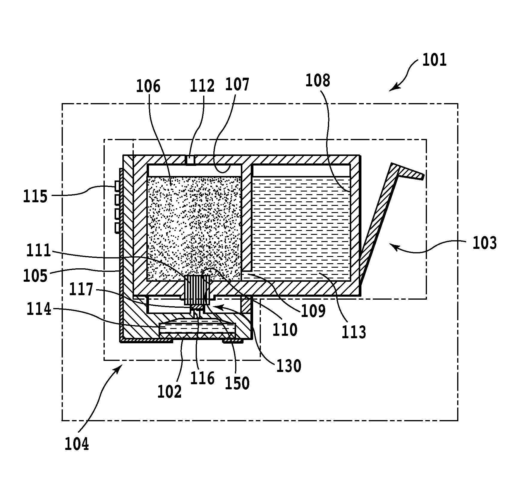
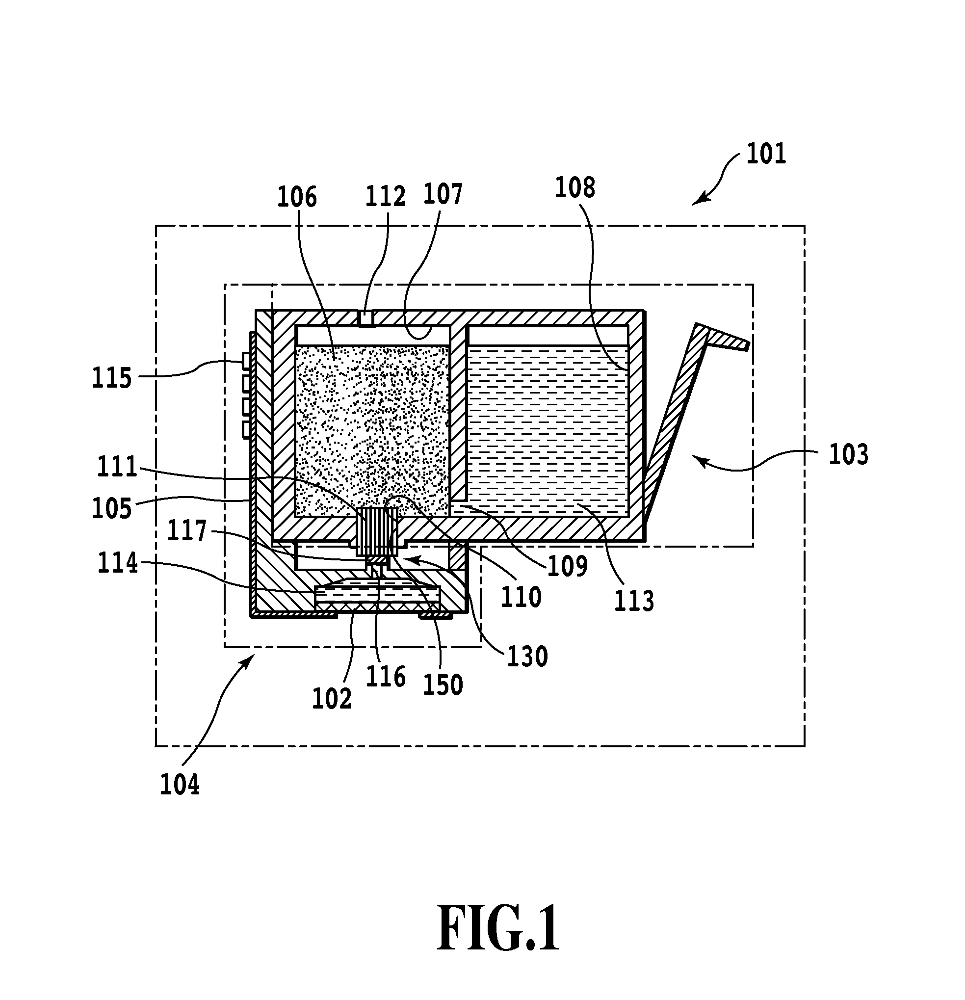
[0040]FIG. 1 is a sectional view of an operative condition of an ink jet cartridge applied to the first embodiment of the present invention and having an ink tank portion and a print head portion which are formed as one member. Since the ink jet cartridge shown in FIG. 1 is in the operative condition, a seal member blocking the print head portion, an ink supply port, and an atmospheric communicating port has already been peeled. In this case, the seal member is not applied to the ink jet cartridge.
[0041]An ink jet cartridge 101 shown in FIG. 1 has an ink tank portion 103 and a print head portion 104. In the present embodiment, the ink tank portion 103 and the print head potion 104 are separately manufactured and then coupled together. The ink tank portion 103 and the print head portion 104 may be integrally formed. The ink tank portion 103 and the print head portion 104 ...
second embodiment
[0071]Now, description will be given of a distribution form of ink jet cartridge according to a second embodiment. Components of the second embodiment which can be configured as in the case of the first embodiment are denoted by the same reference numerals in the drawings. Only differences from the first embodiment will be described.
[0072]FIG. 5 shows the distribution form 401 of ink jet cartridge according to a second embodiment of the present invention. A seal member 126 according to the second embodiment has a seal fold-back part 119 formed thereon where the seal member 126 is folded back into a U shape and thermally welded to the periphery of the ink supply ports 110 in the ink tank portion 103. The seal member 126 is folded back at the seal fold-back part 119, and the fold-back parts of the seal member 126 reach the seal gate portion 125. One of the fold-back parts of the seal member 126 then extends in a direction (the front-back direction of the sheet of the drawing) orthogon...
third embodiment
[0078]Now, description will be given of a distribution form of ink jet cartridge according to a third embodiment. Components of the third embodiment which can be configured as in the case of the first or second embodiment are denoted by the same reference numerals in the drawings. Only differences from the first and second embodiments will be described.
[0079]FIG. 6 shows a distribution form 501 of ink jet cartridge according to the third embodiment of the present invention. A seal member 127 according to the present embodiment is formed of elastomer. The seal member 127 of the compressed elastomer is located in the ink supply path 150 between the ink supply port 110 in the ink tank portion 103 and the print head portion 104.
[0080]An appropriate material for the seal member 127 formed of the elastomer is chlorinated butyl rubber or hydrogenated nitrile rubber (H-NBR), which has an excellent gas barrier property. However, a resin-containing elastomer may be adopted. The seal member 12...
PUM
 Abstract
Description
Claims
Application Information