

Image-taking apparatus capable of distributing taken images over network
- Summary
- Abstract
- Description
- Claims
- Application Information
AI Technical Summary
Benefits of technology
Problems solved by technology
Method used
Image

Examples
embodiment 1
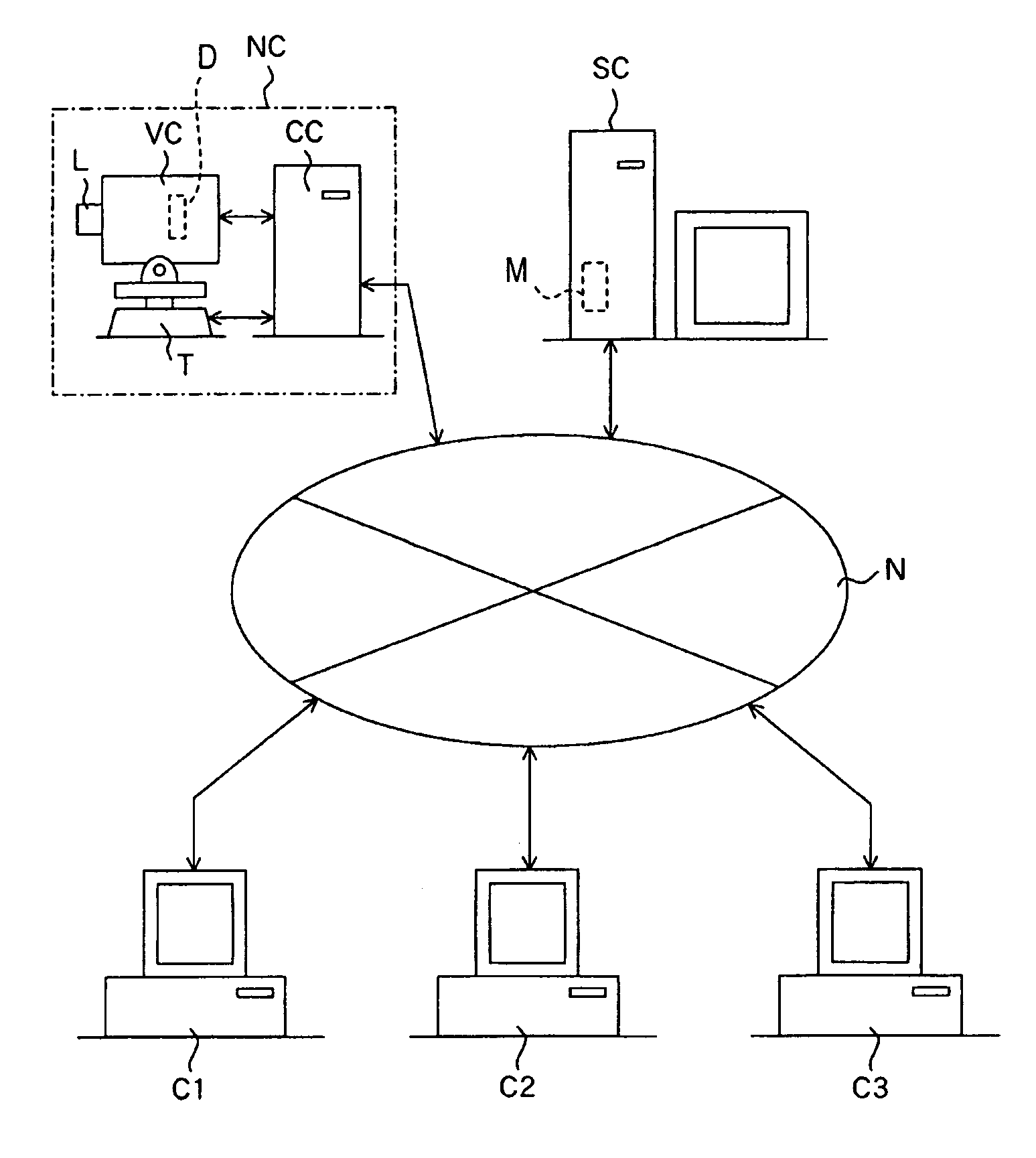
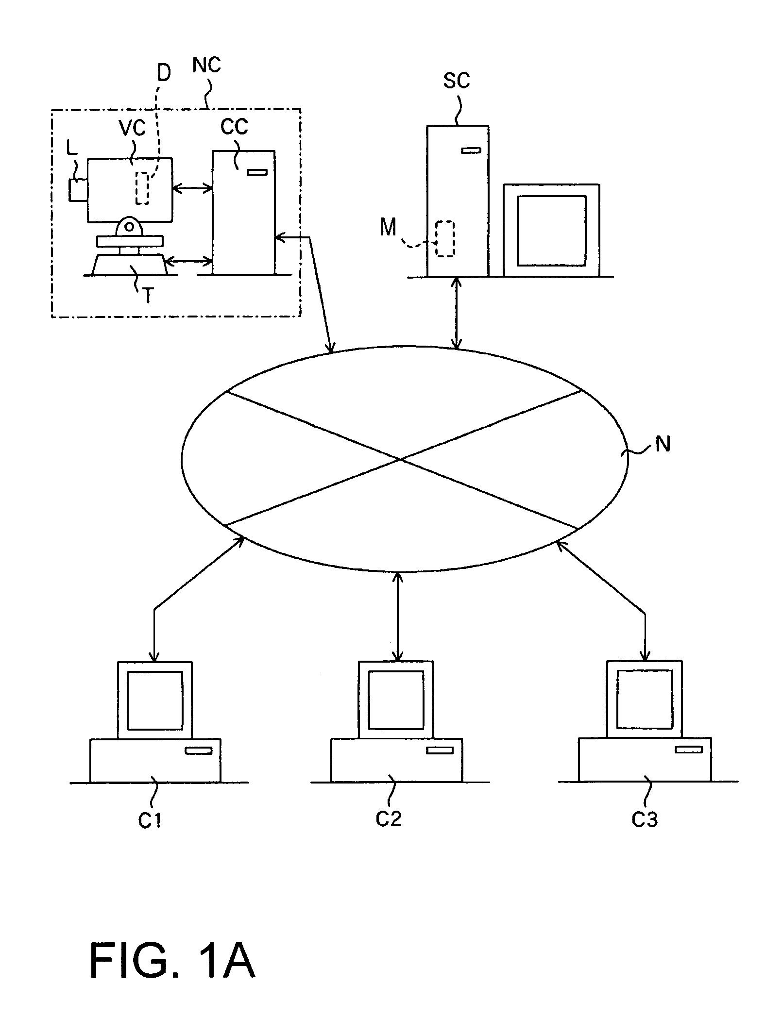
[0036]FIG. 1A schematically illustrates the structure of a network image-taking system using a network camera (image-taking apparatus) according to Embodiment 1. N denotes a network such as a LAN, a WAN, the Internet, or an Ethernet network. It should be noted that this network N is not necessarily a wired network, but may also be a wireless network. VC denotes a video camera which can take moving images and still images.
[0037]The video camera VC is mounted on a pan head T in a busy street or a tourism spot or the like. Panning and tilting is possible by operating the pan head T and zooming is possible by operating an image-taking lens L.
[0038]This video camera VC takes images by photoelectrically converting with an image-pickup device (photoelectric conversion device) D, such as a CCD or CMOS sensor, object images formed with a zoomable image-taking lens (image-taking optical system) L. Moreover, the video camera VC can take the object image in either a first image-taking mode for ...
embodiment 2
[0062]In Embodiment 1, a case has been explained in which it is decided, based on the focal length (image-taking zoom ratio) of the image-taking lens L or the object distance, whether high-resolution image-taking is prohibited or not, but it is also possible to decide whether high-resolution image-taking is prohibited or not, depending on whether the object to be pictured is a specific object, such as a person (in particular, a face).
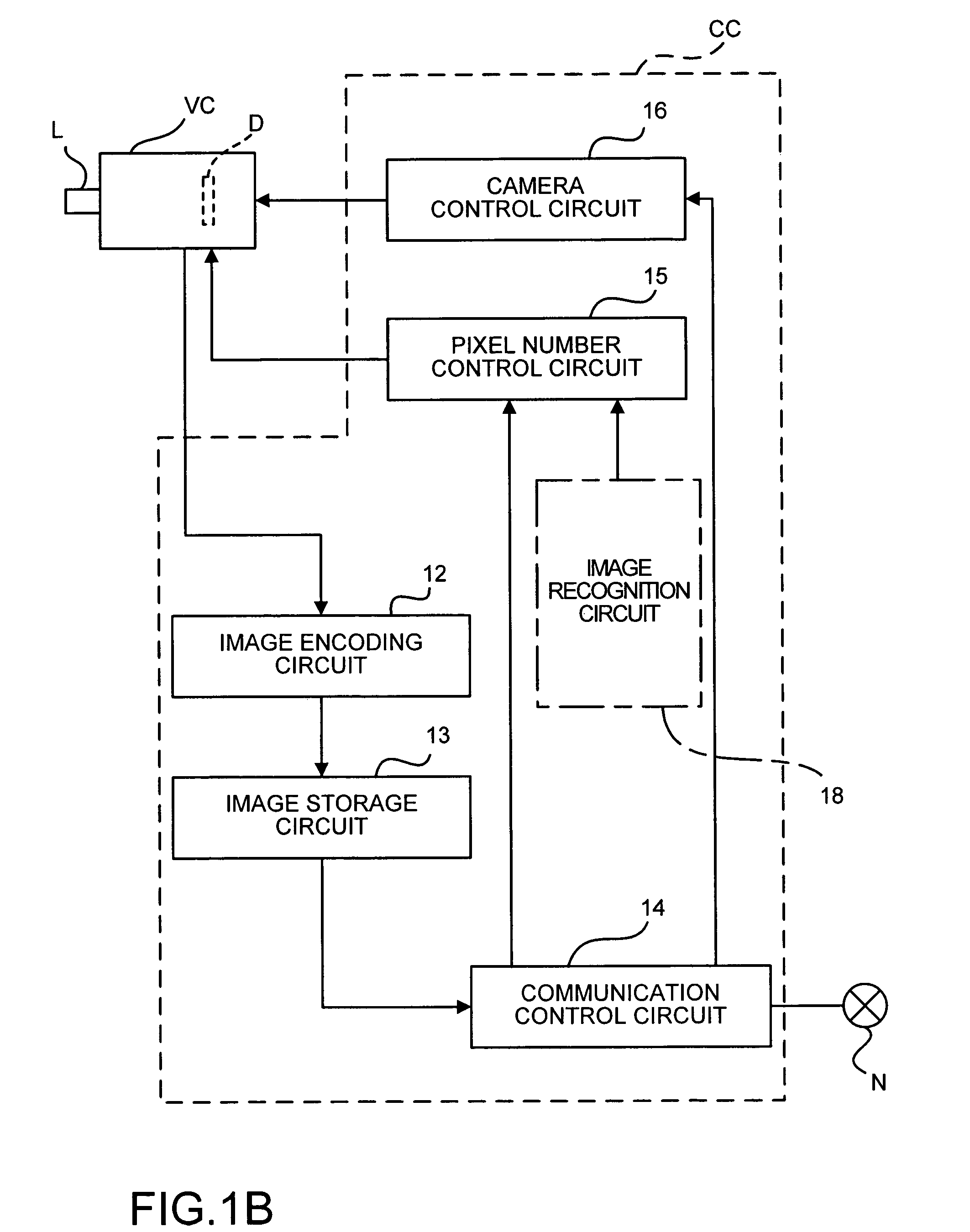
[0063]In that case, an image recognition circuit 18 is provided inside the control computer CC, as shown by a dotted line in FIG. 1B, and it is determined whether there is a specific object in the image-taking field. It should be noted that the image recognition circuit 18 also may be provided outside the control computer CC.
[0064]More specifically, for the image recognition circuit 18, a circuit may be used that can discriminate shapes of objects by edge detection in the image taken at low resolution in the first image-taking mode. When this image reco...
embodiment 3
[0078]In Embodiments 1 and 2, cases have been explained in which image-taking at high resolutions is prohibited in accordance with the result of detecting the focal length of the image-taking lens L or the result of determining the object with an image recognition circuit. This embodiment explains the case that the administrator of the network camera NC can freely set a region at which high-resolution image-taking is prohibited.
[0079]FIG. 6 is a flowchart showing the operation of the network camera NC of Embodiment 3 (mainly the pixel number control circuit 15). It should be noted that the overall structure of the network image-taking system is similar to that of Embodiment 1.
[0080]First, at Step 61, the administrator enters into the control computer CC, via the server computer SC, an administrator password for setting or changing an image-taking restriction condition of the network camera NC in the control computer CC, and if the verification of this password is successful, then th...
PUM
 Abstract
Description
Claims
Application Information