Flat panel speaker mounting system

a speaker and mounting system technology, applied in the direction of transducer details, electrical transducers, electrical apparatus, etc., can solve the problems of no speaker mounting system, mounting system limited adjustment, and technology can never be very thin, so as to facilitate superior sound projection and clarity, and reduce the effect of echoes

Inactive Publication Date: 2008-12-11
LAU KA WAI
View PDF7 Cites 17 Cited by
  • Summary
  • Abstract
  • Description
  • Claims
  • Application Information

AI Technical Summary

Benefits of technology

[0019]The sway arm is affixed, via a pivoting joint, to an intermediate arm to form a sway arm / intermediate arm joint. This joint provides a rotational or pivoting motion which enables one to adjust speaker position in regard to upward / downward tilt (which may also be described as pitch or rotation about the X axis). Independent motion of this joint (motion of this joint while all other pivoting / rotating joints remain in place) will also effect the relative height, depth and upward / downward tilt of speakers mounted upon the device.
[0029]The speaker mounting apparatus of the present invention is especially configured and adapted to include flat panel mounting holes which align with and enable the apparatus to be affixed to flat panel display utilizing VESA mounting hole configurations and dimensions. Thus, the apparatus of the present invention may be mounted to such displays by means of threaded mounting holes provided in a plate locate in the back panel of such displays in accordance with the aforementioned VESA conventions and standards. The apparatus of the present invention, as described in much greater detail below, can be mounted to such displays via the VESA mounting holes without interfering with, and, in desired, in conjunction with wall, ceiling or pedestal type mounts also affixed to these same VESA mounting holes. Thus, the apparatus of the present invention provides a convenient and reliable means for affixation of the speaker mount to flat panel displays.

Problems solved by technology

This technology can never be very thin (relative to flat panel display devices) in that cathode ray tubes generate light via the process of cathodoluminescence.
However, the majority of such devices include “audio out” terminals to which external speakers may be attached.
However, such mounting systems have been limited in providing limited adjustment as to the position of the speaker in relation to the display.
Also, heretofore, no speaker mounting system has been disclosed which easily and securely mounts to the majority of flat panel televisions and monitors.

Method used


Image

  • Flat panel speaker mounting system
  • Flat panel speaker mounting system
  • Flat panel speaker mounting system

Examples


Embodiment Construction

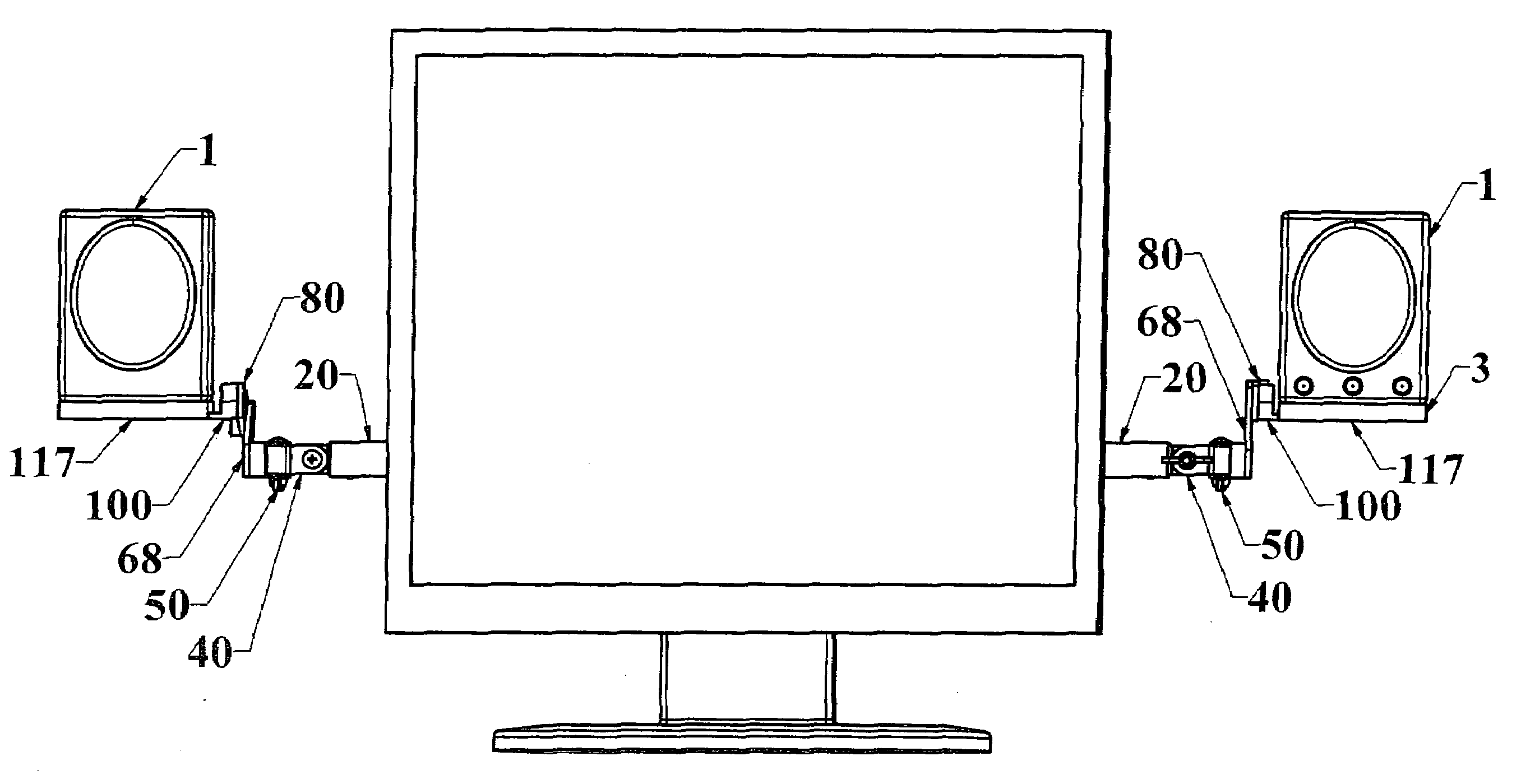
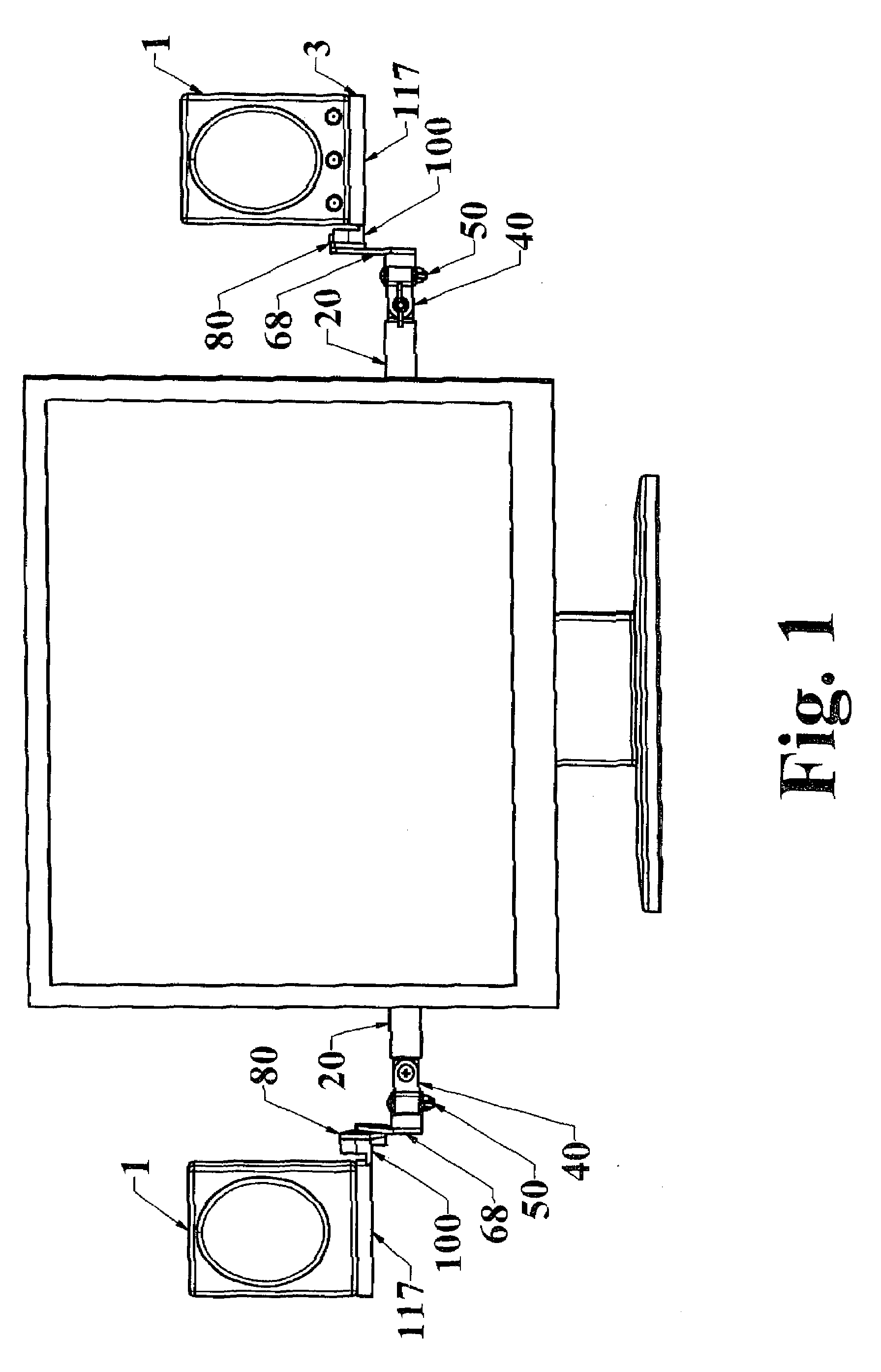
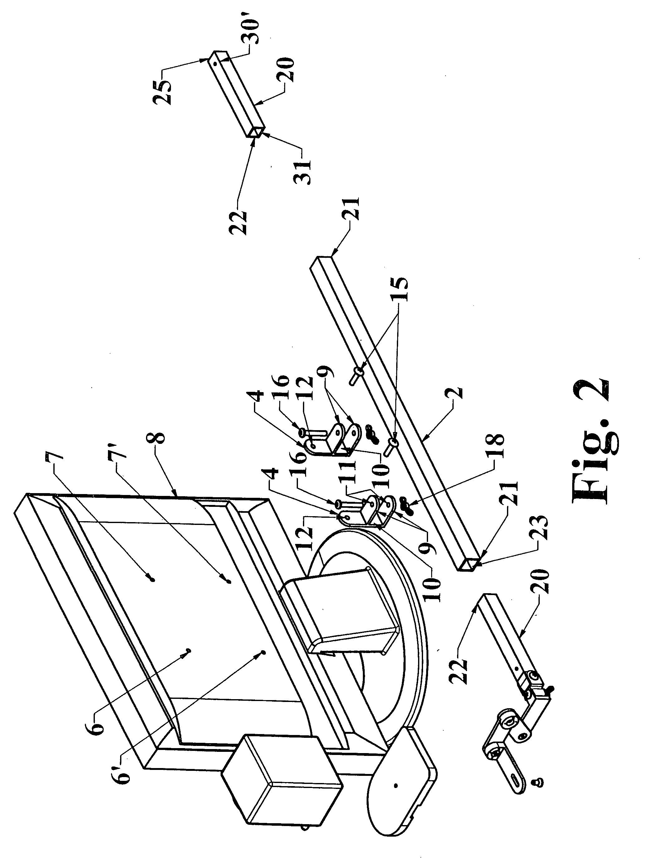
[0039]In a first preferred embodiment of the present invention, an apparatus for mounting at least two speakers to a flat panel display device is provided wherein said device may be affixed to a flat panel display utilizing standardized threaded mounting holes provided in said flat panel devices (also known as VESA compliant mounting holes) and wherein the apparatus enables adjustment of the position of each of said at least two speakers relative to the flat panel display in regard to speaker separation, speaker height, speaker depth; inward / outward tilt, upward / downward tilt and left / right cant. The first preferred embodiment of the present invention—as all embodiments thereof—may be utilized in conjunction, or independent of flat panel mounting devices such as, for example, pedestal, wall and ceiling mounts (as discussed above and below.)

[0040]The first preferred embodiment of the present invention, as illustrated in FIGS. 1-5, provides an apparatus for mounting at least two speak...


PUM


Abstract

An apparatus for mounting two speakers to a flat panel display device is disclosed wherein the device, utilizing standardized mounting plates provided in such flat panel display devices, enables the mounting of two speakers while providing the ability to change speaker position in regards to six different position parameters. The apparatus may be utilized in conjunction with flat panel mounting devices, such as pedestal, wall or ceiling mounts, or utilized independently thereof. More specifically, the device further provides independent adjustment of the position of each speaker mounted thereby in regard to height, fore / aft and depth position, as well as rotation about an X, Y and Z axis. The device enables one to make changes in—regard to the position of a speaker—or other peripheral devices mounted thereon—relative to one or more of the aforementioned movements without altering other aspects of speaker position, if desired.

Description

TECHNICAL FIELD[0001]The apparatus disclosed herein relates most closely to the technical field of speaker mounting devices. More specifically, the present apparatus relates to the field of devices utilized for mounting speakers—as well as other peripheral devices—to any type or form of flat panel display devices such as, for example, LCD monitors and televisions.BACKGROUND OF THE ART[0002]The term “flat panel display device” refers to an electronic display in which a large orthogonal array of display elements, such as liquid-crystal (e.g., LCD) or electro luminescent (e.g., plasma) elements, form a flat screen. The term “flat-panel display” is somewhat deceptive in that it is the thinness of the display that is the paramount characteristic. In the past, both television sets and computer monitors commonly utilized cathode-ray tubes. This technology can never be very thin (relative to flat panel display devices) in that cathode ray tubes generate light via the process of cathodolumin...

Claims


Application Information

Patent Timeline
Patent Type & Authority Applications(United States)
IPC IPC(8): H04R1/02
CPCH04R1/026
Inventor LAU, KA WAI
Owner LAU KA WAI
Why Eureka
Try Eureka