

Speaker
a technology of speaker and diaphragm, applied in the field of speaker, can solve the problems of affecting the appearance and affecting the sound quality of the speaker, and the diaphragm becoming soft, etc., and achieves the effect of simple structure, large input, and avoiding the sacrifice of appearance and sound quality
- Summary
- Abstract
- Description
- Claims
- Application Information
AI Technical Summary
Benefits of technology
Problems solved by technology
Method used
Image

Examples
first embodiment
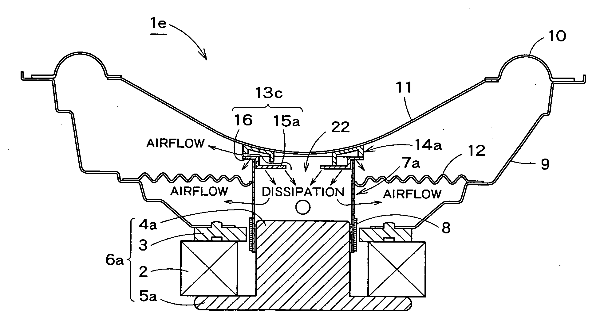
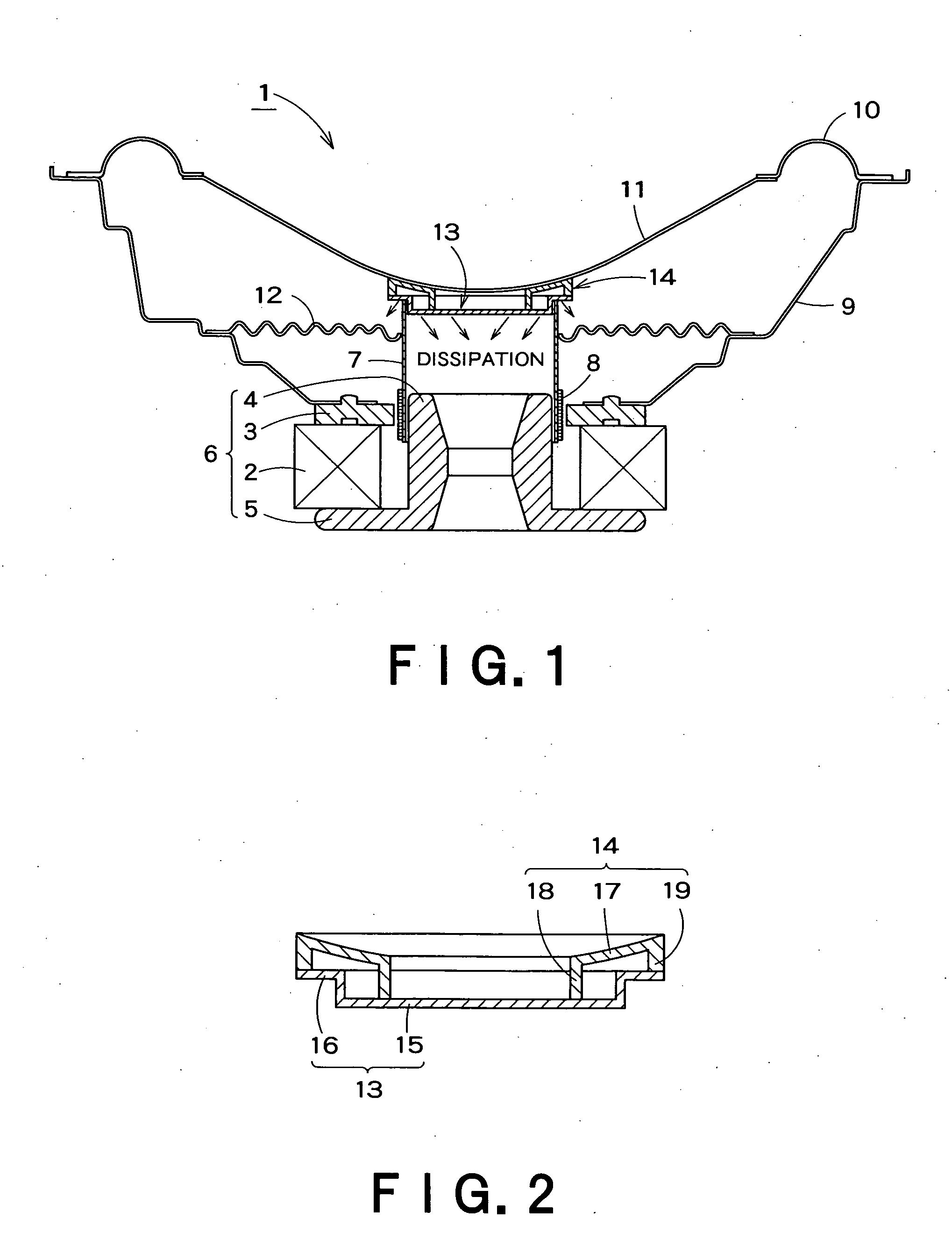
[0041]Thus, in the speaker 1 the heat sink 13 and the coupler 14 are disposed between the bobbin 7 and the diaphragm 11, and the heat generated in the voice coil 8 is dissipated efficiently via the heat sink 13. As a result, the speaker 1 has a simple structure and at the same time can withstand a large input by suppressing the heat generated in the voice coil 8 from conducting to the diaphragm 11 wherein its appearance and sound quality are not impaired.
[0042]Also, the coupler 14 facilitates the process of bridging between the diaphragm 11 and the heat sink 13. If the diaphragm 11 is to be attached directly to the heat sink 13 without the coupler 14, it is difficult to position the diaphragm 11, thus raising a workability problem. Since the coupler 14 in the present embodiment is previously provided with the diaphragm supporting portion 17 for receiving the diaphragm 11 and the inner and outer circular walls 18 and 19 for connection to the heat sink 13, the positioning between the...
second embodiment
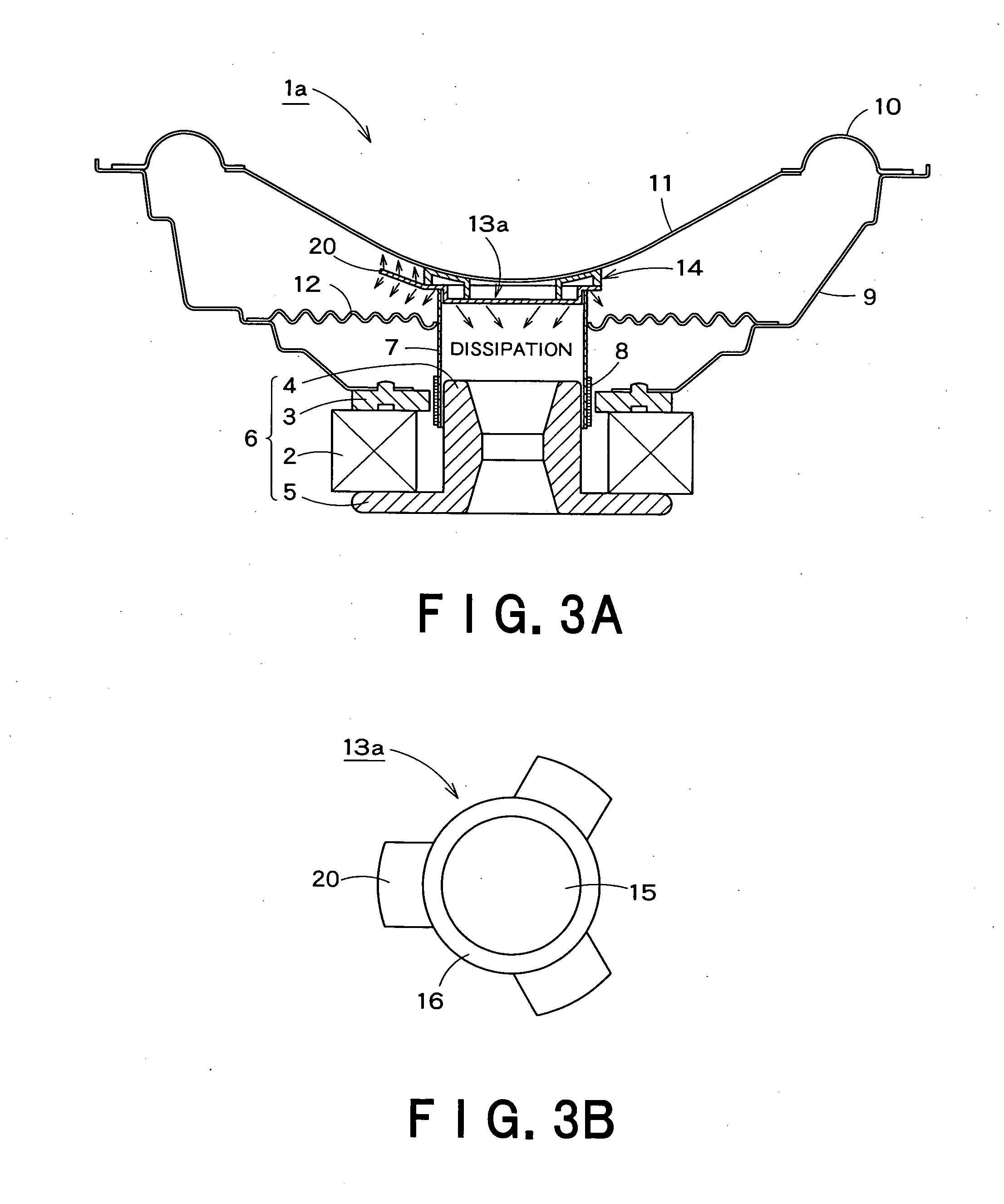
[0044]the present invention will be described with reference to FIGS. 3A and 3B. A speaker 1a according to the second embodiment differs from the speaker 1 of the first embodiment only in heat sink structure, and description will be focused on the difference wherein any component parts corresponding to those in FIGS. 1 an 2 are denoted by the same reference numerals, and a detailed description thereof will be omitted below.
[0045]Referring to FIGS. 3A and 3B, a heat sink 13a of the speaker 1a includes, in addition to a base portion 15 and a flange portion 16, a plurality (three in FIG. 3B) of fins 20 each having a substantially rectangular shape and extending radially outwardly from the outer circumference of the flange portion 16. Otherwise, the speaker 1a according to the second embodiment is the same as the speaker 1 according to the first embodiment.
[0046]Since the heat sink 13a has a larger surface area than the heat sink 13 by the aggregate surface area of the fins 20, the heat...
third embodiment
[0048]the present invention will be described with reference to FIGS. 4A and 4B. A speaker 1b according to the third embodiment is similar to the speaker 1a of the second embodiment but differs therefrom in fin structure for a heat sink, and description will be focused on the difference wherein any component parts corresponding to those in FIGS. 3A and 3B are denoted by the same reference numerals, and a detailed description thereof will be omitted below.
[0049]Referring to FIGS. 4A and 4B, a heat sink 13b of the speaker 1b includes a base portion 15, a flange portion 16, and a plurality (three in FIG. 4B) of fins 20a which each have a substantially rectangular shape, extend radially outwardly from the outer circumference of the flange portion 16, and which have a wave-shaped surface 21 thereby increasing its surface area. Otherwise, the speaker 1b according to the second embodiment has the same structure as the speaker 1a according to the second embodiment in which the fins 20 of th...
PUM
 Abstract
Description
Claims
Application Information