Tire

a technology of tires and rolling bars, applied in the field of tires, can solve the problems of failures that cannot be effectively suppressed, failures as described above, etc., and achieve the effect of preventing failures and ensuring safety

Pending Publication Date: 2022-03-31
BRIDGESTONE CORP
View PDF2 Cites 0 Cited by
  • Summary
  • Abstract
  • Description
  • Claims
  • Application Information

AI Technical Summary

Benefits of technology

[0008]Accordingly, an object of the present invention is to provide a tire that can more reliably prevent the occurrence of a failure in the vicinit

Problems solved by technology

However, it has been found that even in the tire in which the measures for preventing the occurrence of the failure in the vicinity of the outer edge of the tire width direction of the belt layer are taken as described above, the occurrence of the failure may not nec

Method used


Image

  • Tire
  • Tire
  • Tire

Examples


Embodiment Construction

[0017]Embodiments will be described below with reference to the drawings. The same functions and configurations are denoted by the same or similar reference numerals, and descriptions thereof are omitted as appropriate.

(1) Overall Structure of Tire

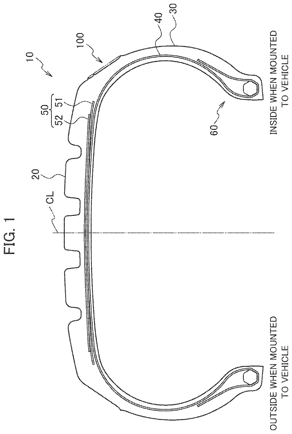
[0018]FIG. 1 is a sectional view of the pneumatic tire 10 according to the present embodiment. Specifically, FIG. 1 is a cross-sectional view of the pneumatic tire 10 taken along tire width direction and tire radial direction. In FIG. 1, the sectional hatching is not shown (hereinafter the same).

[0019]The pneumatic tire 10 can be used for a standard four-wheel passenger vehicle, and can be suitably used for a high-performance automobile having particularly high vehicle dynamics.

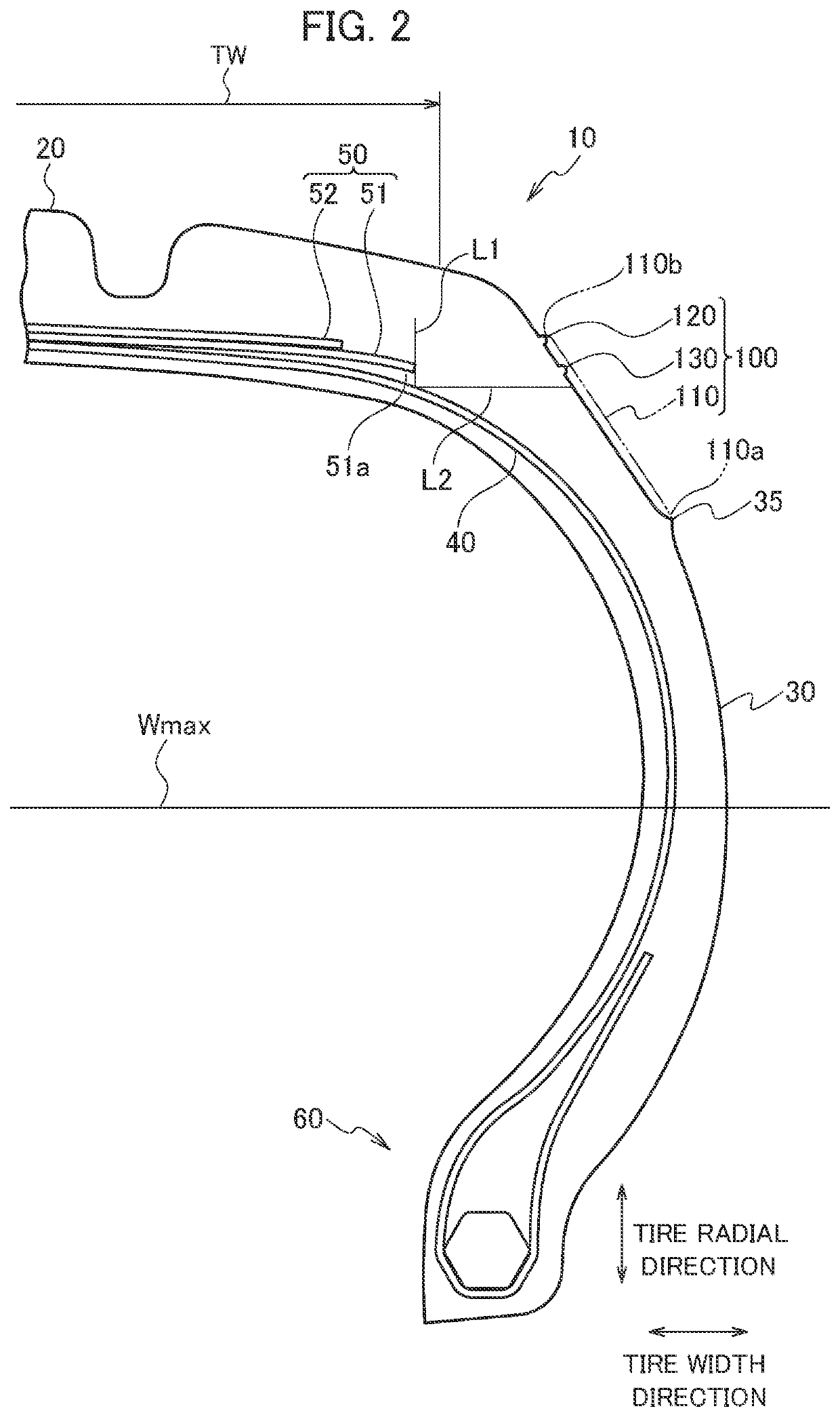
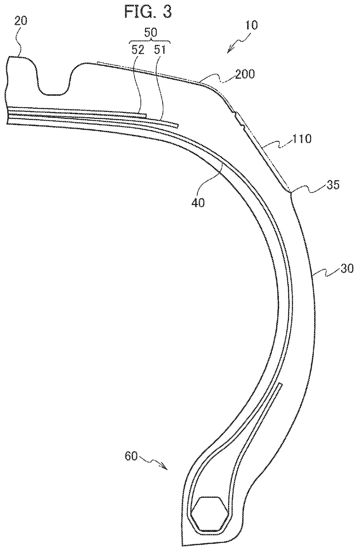
[0020]As shown in FIG. 1, the pneumatic tire 10 includes a tread 20, a tire side portion 30, a carcass 40, a belt layer 50 and a bead portion 60.

[0021]The tread 20 is a portion in contact with the road surface. On the tread 20, a pattern (not shown) is formed accord...


PUM

PropertyMeasurementUnit
Widthaaaaaaaaaa

Abstract

A pneumatic tire includes a longitudinal ridge extending along the tire radial direction and projecting outward from the surface of the tire side portion toward an outside of a tire width direction. A plurality of longitudinal ridges are provided along the tire circumferential direction, and a tire radial direction inner end of the longitudinal ridge is located outside the tire radial direction than the maximum width position. The tire radial direction outer end of the longitudinal ridge is located outside the tire radial direction than a straight line L2 orthogonal to a straight line L1.

Description

TECHNICAL FIELD[0001]The present invention relates to a tire capable of suppressing the occurrence of a failure in the vicinity of the outer end of the tire width direction of a belt layer.BACKGROUND ART[0002]Conventionally, in a pneumatic tire (hereinafter abbreviated as tire) having a belt layer on the inner side of a tire radial direction of a tread contacting a road surface, various measures have been taken to prevent the occurrence of a failure in the vicinity of the outer end of the tire width direction of the belt layer.[0003]For example, in a tire having a belt layer including a pair of crossing belts and a spiral belt having a cord extending to the tire circumferential direction, a method is known for optimizing the positions of the outer ends of the tire width direction of the crossing belts and the spiral belts, and the elastic modulus of the cords forming the crossing belts (see Patent Literature 1).[0004]According to such tire, it is possible to effectively suppress fai...

Claims


Application Information

Patent Timeline
IPC IPC(8): B60C13/02
CPCB60C13/02B60C2013/026B60C11/01B29D30/0606B29D30/0629B29D2030/0612Y02T10/86
Inventor OGAWA, YUYA
Owner BRIDGESTONE CORP
Why Eureka
Try Eureka