Clutch control apparatus for vehicle

a technology for controlling apparatus and clutch, which is applied in the direction of fluid-actuated clutches, clutches, non-mechanical actuated clutches, etc., can solve the problems of deterioration in the operability of the piston, oil leakage from the seal member of the hydraulic cylinder, so as to suppress the increase in the sliding resistance of the piston to the housing slide surface, the effect of not enhancing the sealability

Active Publication Date: 2014-12-16
NISSAN MOTOR CO LTD
View PDF15 Cites 0 Cited by
  • Summary
  • Abstract
  • Description
  • Claims
  • Application Information

AI Technical Summary

Benefits of technology

[0005]Specifically, when the rotation speed (or the rotation number) is increased under a condition where the piston is pressed back, that is, under a condition that a hydraulic pressure in a hydraulic cylinder is kept at zero, vibration inputted to the piston becomes larger to thereby cause oil leakage from a seal member of the hydraulic cylinder. Incidentally, in a case where a tension of the lip seal per se, for instance, a rigidity of the lip seal per se, is increased in order to ensure the tension of the lip seal under the condition that the piston is pressed back, the lip seal becomes harder. This thereby increases a resistance to the piston during slide movement of the piston, which results in deterioration in operability of the piston.
[0006]In contrast, the present invention provides embodiments of a clutch control apparatus for a vehicle intended to suppress oil leakage from a seal member of a hydraulic cylinder even when vibration is inputted to the piston upon transmitting a driving force, without enhancing a per se sealability of the seal member.
[0008]In one clutch control apparatus according to the present invention, upon engagement of the clutch, the pressure holding controller applies a hydraulic pressure for retaining a sealability of the seal member to the piston chamber of the hydraulic cylinder while maintaining the engagement condition of the clutch. Specifically, upon engagement of the clutch, the hydraulic pressure for retaining a sealability of the seal member is intentionally applied to the piston chamber of the hydraulic cylinder, regardless of that it is of a normally-closed type, so that the tension of the seal member (i.e., a pressing force of the seal member relative to the housing slide surface) becomes larger than that caused where the hydraulic pressure is not applied to the piston chamber. Accordingly, even where a vibration component of a driving force is inputted to the piston of the hydraulic cylinder via the elastic member through the engaged clutch, it is possible to suppress oil leakage from a seal member of the hydraulic cylinder. Further, since the seal member is not enhanced in sealability per se, an increase in sliding resistance of the piston to the housing slide surface can be suppressed upon disengagement of the clutch to thereby ensure a smooth movement of the piston.

Problems solved by technology

When vibration is inputted to the piston under the condition that the piston is pressed back, oil leakage is caused due to a lack of the tension of the lip seal.
Specifically, when the rotation speed (or the rotation number) is increased under a condition where the piston is pressed back, that is, under a condition that a hydraulic pressure in a hydraulic cylinder is kept at zero, vibration inputted to the piston becomes larger to thereby cause oil leakage from a seal member of the hydraulic cylinder.
This thereby increases a resistance to the piston during slide movement of the piston, which results in deterioration in operability of the piston.

Method used


Image

  • Clutch control apparatus for vehicle
  • Clutch control apparatus for vehicle
  • Clutch control apparatus for vehicle

Examples


Embodiment Construction

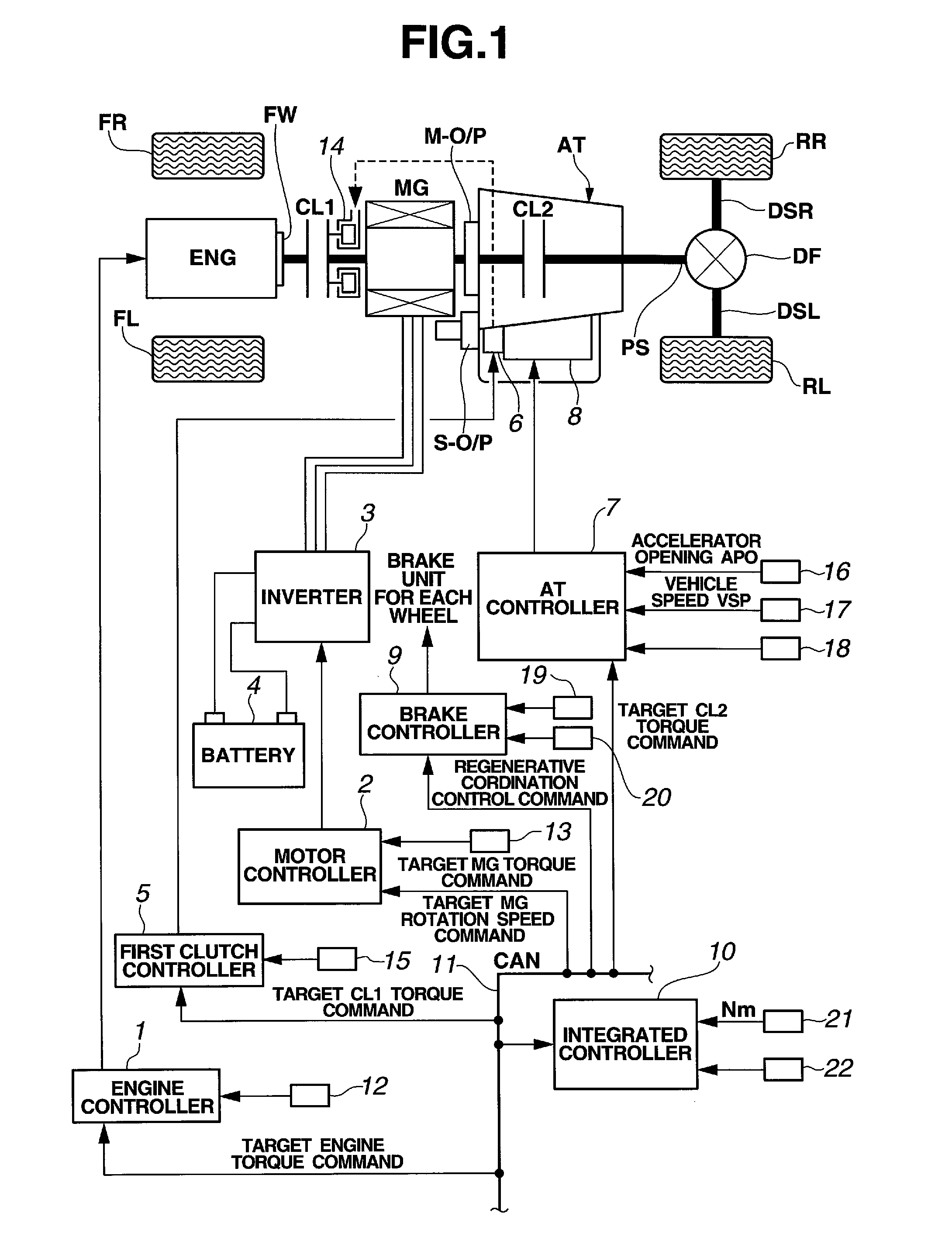
[0025]First, the construction of the clutch control apparatus for a vehicle according to embodiments of the present invention will be explained with reference to FIG. 1.

[0026]As shown in FIG. 1, a drivetrain of a FR hybrid vehicle that can incorporate embodiments of the invention includes engine ENG (driving power source), flywheel FW, first clutch CL1 (clutch), motor / generator MG, second clutch CL2, automatic transmission AT, propeller shaft PS, differential DF, left drive shaft DSL, right drive shaft DSR, left rear wheel RL (driving wheel) and right rear wheel RR (driving wheel). Further, FL denotes a left front wheel, FR denotes a right front wheel, M-O / P denotes a main oil pump and S-O / P denotes a sub-oil pump.

[0027]Engine ENG may be a gasoline engine or a diesel engine. Engine start control, engine stop control, etc., are carried out on the basis of engine control commands outputted from engine controller 1. Flywheel FW is disposed on an engine output shaft.

[0028]First clutch C...


PUM


Abstract

Taught herein is a clutch control apparatus that suppresses oil leakage from a seal member of a hydraulic cylinder even when vibration occurs, without enhancing sealability of the seal member per se. The clutch control apparatus includes normally-closed first clutch, a hydraulic cylinder, a piston, a lip seal and a pressure holding control section. The first clutch is disposed between an engine and driving wheels and is held in engagement by an elastic force applied to the first clutch CL1 by a diaphragm spring. The lip seal is disposed on the piston and enhances sealability between the piston and a housing slide surface in accordance with an increase in hydraulic pressure in the piston chamber. When the first clutch is engaged, the pressure holding control section applies a hydraulic pressure to retain the sealability of the lip seal to the piston chamber while maintaining engagement of the first clutch.

Description

CROSS-REFERENCE TO RELATED APPLICATIONS[0001]This application claims priority from Japanese Patent Application Serial No. 2010-210406, filed Sep. 21, 2010, which is incorporated herein in its entirety by reference.TECHNICAL FIELD[0002]The present invention relates to a clutch control apparatus for a vehicle that includes a normally-closed clutch in a drivetrain from a driving power source to driving wheels.BACKGROUND[0003]Japanese Patent Application Unexamined Publication No. 2004-19744 discloses a clutch apparatus accommodated in a clutch housing in which a piston of a hydraulic cylinder is movable to abut on a release bearing contacted with a diaphragm spring, and thereby allows a clutch disk to be disengaged from a pressure plate.BRIEF SUMMARY[0004]In the conventional clutch apparatus described above, hydraulic pressure is not applied to the piston under a condition that the piston is pressed back into the hydraulic cylinder by the diaphragm spring of the clutch. Therefore, a ten...

Claims


Application Information

Patent Timeline
Patent Type & Authority Patents(United States)
IPC IPC(8): F16D25/04F16D25/08F16D48/06
CPCF16D25/087F16D25/04F16D48/066F16D2500/1026F16D2500/501F16D2500/70406F16D25/08F16D48/06
Inventor OGATA, MAKOTOSUWABAYASHI, AKIRA
Owner NISSAN MOTOR CO LTD
Why Eureka
Try Eureka