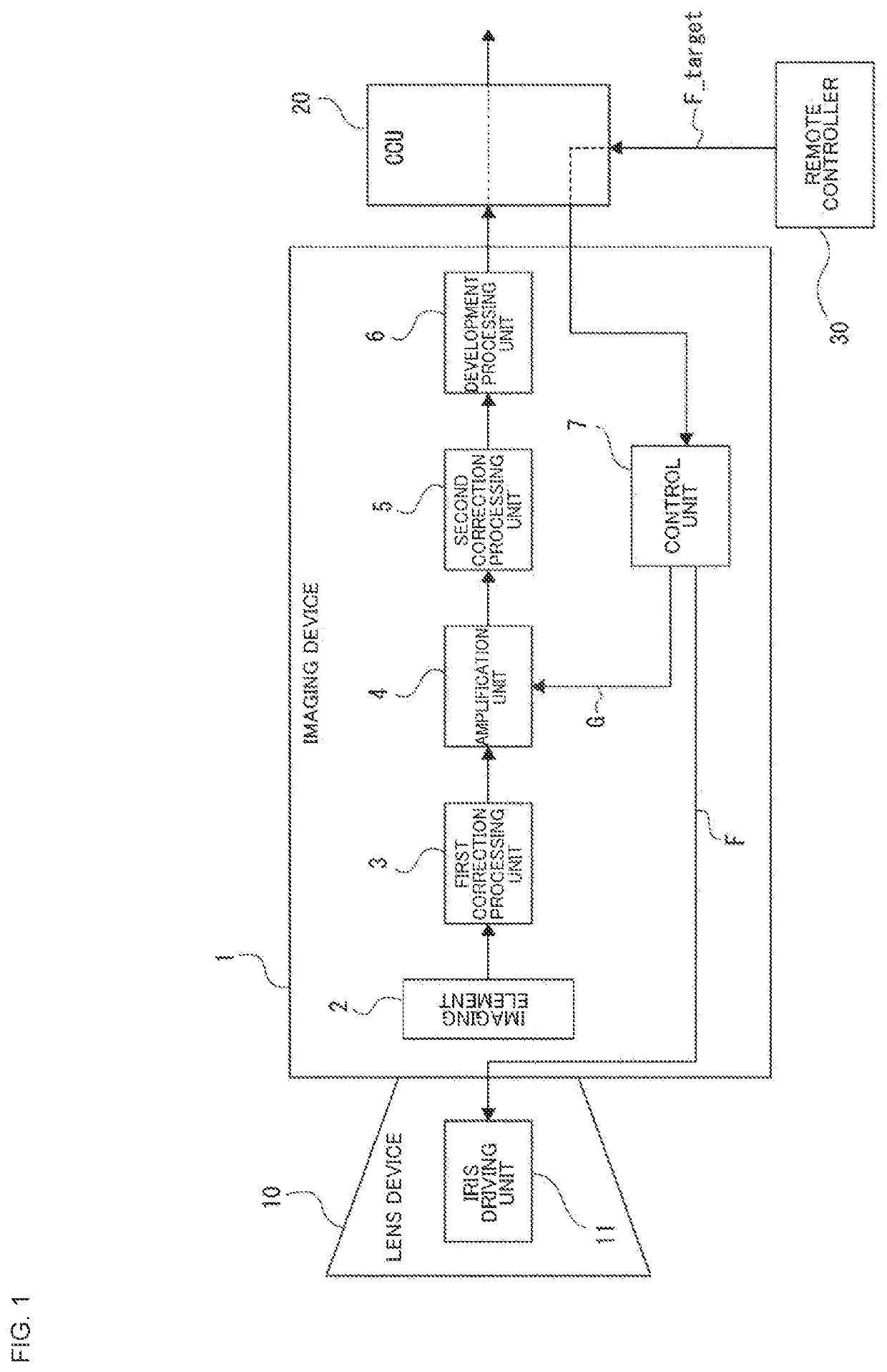
Signal processing device, imaging device, and signal processing method
a signal processing and imaging device technology, applied in the field of signal processing devices, imaging devices, and signal processing methods, can solve problems such as ruffling images, unsuitable, and discontinuity between
- Summary
- Abstract
- Description
- Claims
- Application Information
AI Technical Summary
Benefits of technology
Problems solved by technology
Method used
Image
Examples
first modified example
[3-1. First Modified Example]
[0082]Meanwhile, embodiments are not limited to the aforementioned specific examples and various modified examples may be conceived.
For example, the filter characteristics of the filter unit 7b, that is, delay characteristics of the gain G can be caused to be variable.
As an example, it is conceivable that these delay characteristics are caused to be variable in response to characteristics of the iris in the lens device 10.
[0083]FIG. 9 is a diagram for describing a configuration of an imaging system as a first modified example. Meanwhile, in the following description, parts similar to those that have already been described above will be denoted by the same reference numerals and signs, and description thereof will be omitted.
Here, illustration of the CCU 20 and the remote controller 30 is omitted in FIG. 9.
[0084]In the first modified example, a lens device 10A in which information representing the filter characteristics of the filter unit 7b is stored is ...
second modified example
[3-2. Second Modified Example]
[0089]In addition, it is also conceivable to delay not only the gain G side but also the iris side (F value side). Specifically, a filter unit 7c that delays the F value output from the switching unit 7a is provided along with the filter unit 7b that delays the target value G_target of the gain G as in a control unit 7B shown in FIG. 10. According to this configuration, change in the F value with respect to change in the target value F_target as a brightness indication value is delayed in optical brightness adjustment. Although not illustrated, the F value (represented by “F”' in the figure) that has passed through the filter unit 7c is indicated to the iris driving unit 11 in the imaging system in this case.
[0090]According to this, on the assumption that there are ideal iris response characteristics, for example, it is possible to cause total characteristics of “iris+filter” to be identical to the ideal iris response characteristics by applying a filte...
application examples
5. Application Examples
[0108]The technology according to the present disclosure can be applied to various products. For example, the technology according to the present disclosure may be applied to an operating room system.
[0109]FIG. 13 is a diagram schematically illustrating an overall configuration of an operating room system 5100 to which the technology according to the present disclosure is applied. Referring to FIG. 13, the operating room system 5100 is configured by connecting a group of devices provided in an operating room in a coordinated manner via an audiovisual controller (AV Controller) 5107 and an operating room control device 5109.
[0110]Various devices can be installed in the operating room. In FIG. 13, as an example, various device groups 5101 for endoscopic surgery, a ceiling camera 5187 provided on a ceiling of the operating room to image hands of a surgeon, an operating room camera 5189 provided on the ceiling of the operating room to image a state of the entire o...
PUM
 Abstract
Description
Claims
Application Information
 - R&D
- Intellectual Property
- Life Sciences
- Materials
- Tech Scout
- Unparalleled Data Quality
- Higher Quality Content
- 60% Fewer Hallucinations
Browse by: Latest US Patents, China's latest patents, Technical Efficacy Thesaurus, Application Domain, Technology Topic, Popular Technical Reports.
© 2025 PatSnap. All rights reserved.Legal|Privacy policy|Modern Slavery Act Transparency Statement|Sitemap|About US| Contact US: help@patsnap.com


