Joint driving apparatus for robot

a technology of joint driving and robot, which is applied in the direction of joints, gearing, program-controlled manipulators, etc., can solve the problems of reducing the sealing stability, difficult to maintain stable sealing characteristics for a long time, and large seal area, etc., to achieve small radius, small wear, and very slowly rota

Active Publication Date: 2008-12-11
SUMITOMO HEAVY IND LTD
View PDF2 Cites 7 Cited by
  • Summary
  • Abstract
  • Description
  • Claims
  • Application Information

AI Technical Summary

Benefits of technology

[0018]Since the center shaft member is integrally formed with the “output member”, it originally rotates very slowly. Further, since the center shaft member is located at a place closest to the center of the reduction mechanism (while a member integrally rotating with the output member arranged at the side of the external gear in the axial direction), the peripheral speed of the center shaft member is much slower than at the outer peripheral portion of the output member positioned at the side of the external gear. Therefore, the oil seal is extremely small in wear and greatly improved in endurance. Further, the oil seal can be made smaller in radius, thus making it possible to reduce a seal area (sliding area) and maintain the sealing performance at a higher level.
[0019]Further, the center shaft member integrally formed with the output member (moving slowly) is arranged at the center part of the reduction mechanism, thereby when a wiring for a robot is allowed to pass through a through hole of the center shaft member, the wire harness can be effectively prevented from being severely worn.
[0020]In addition, in a case where a clearance is sealed between the output member and the first member positioned outside the external gear in the axial direction, the output member is casted, with the dimensions taken into account. Conventionally, when the thus casted output member has been used as a sliding plane, there is often found a porous area (small holes) on the sliding plane, to result in leakage. Furthermore, when the oil seal is slid on the casted portion, wear and damage easily occur to the oil seal. In the present invention, the shaft portion of the center shaft member integrally formed with the output member can be used as a sliding plane, thus making it possible to easily select materials other than a casting. For example, when steel or the like is used as a material of the center shaft member, the above-conventional problem due to the casted sliding plane is easily eliminated.
[0021]According to the present invention, a high sealing performance can be maintained for a long time, and a wire harness in a center shaft member can be prevented from being worn.

Problems solved by technology

However, in the above constitution, the oil seals 44A, 44B are extremely large in diameter to result in a larger seal area, thus easily lowering the sealing stability against leakage.
Further, although the output members (the first and second carriers 32A, 32B) are basically low in peripheral speed, a fast speed is found at the outer peripheral portion where the diameter is large, thereby easily causing wear due to sliding motions.
Thus, a problem is posed that the service life of the oil seals 44A, 44B is shortened, thereby, making it difficult to maintain stable sealing characteristics for a long time.

Method used


Image

  • Joint driving apparatus for robot
  • Joint driving apparatus for robot
  • Joint driving apparatus for robot

Examples


Embodiment Construction

[0028]Exemplary embodiments of the present invention will now be described in detail with reference to the accompanying drawings.

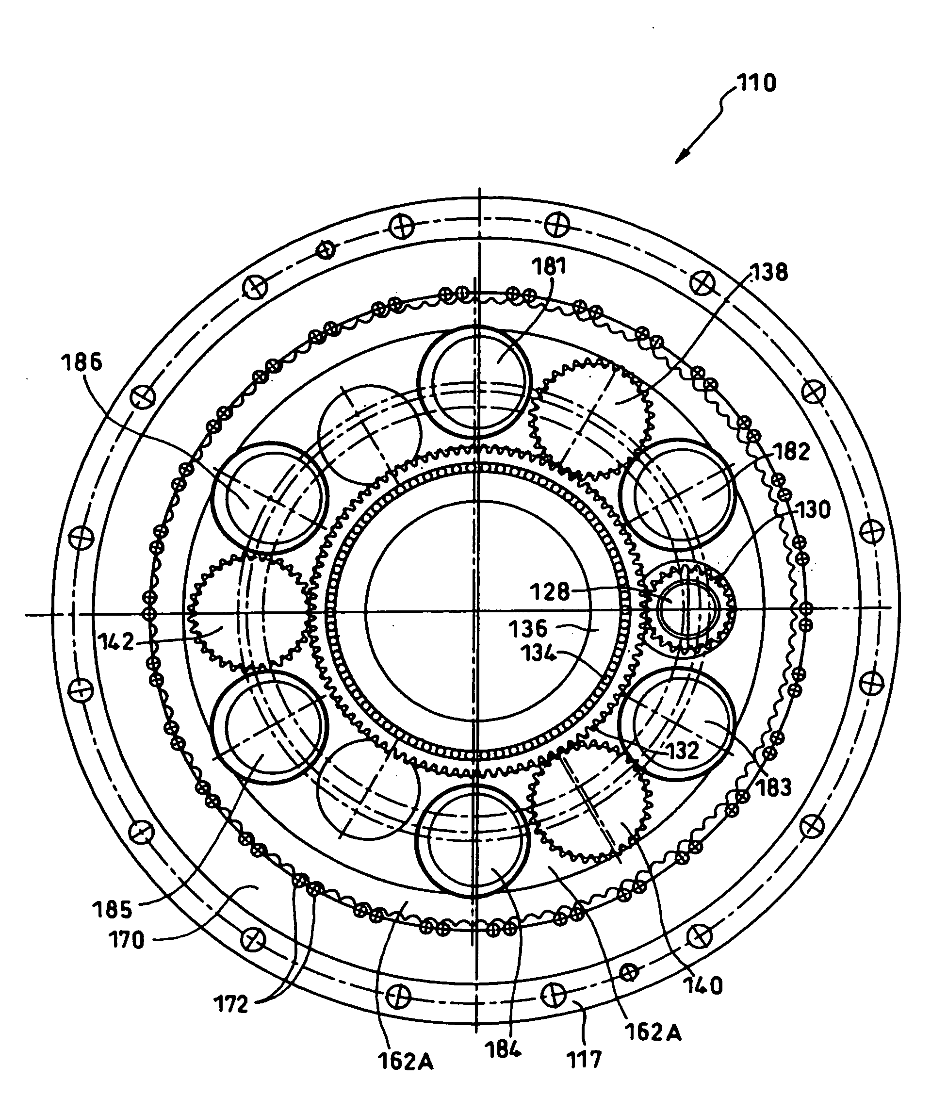
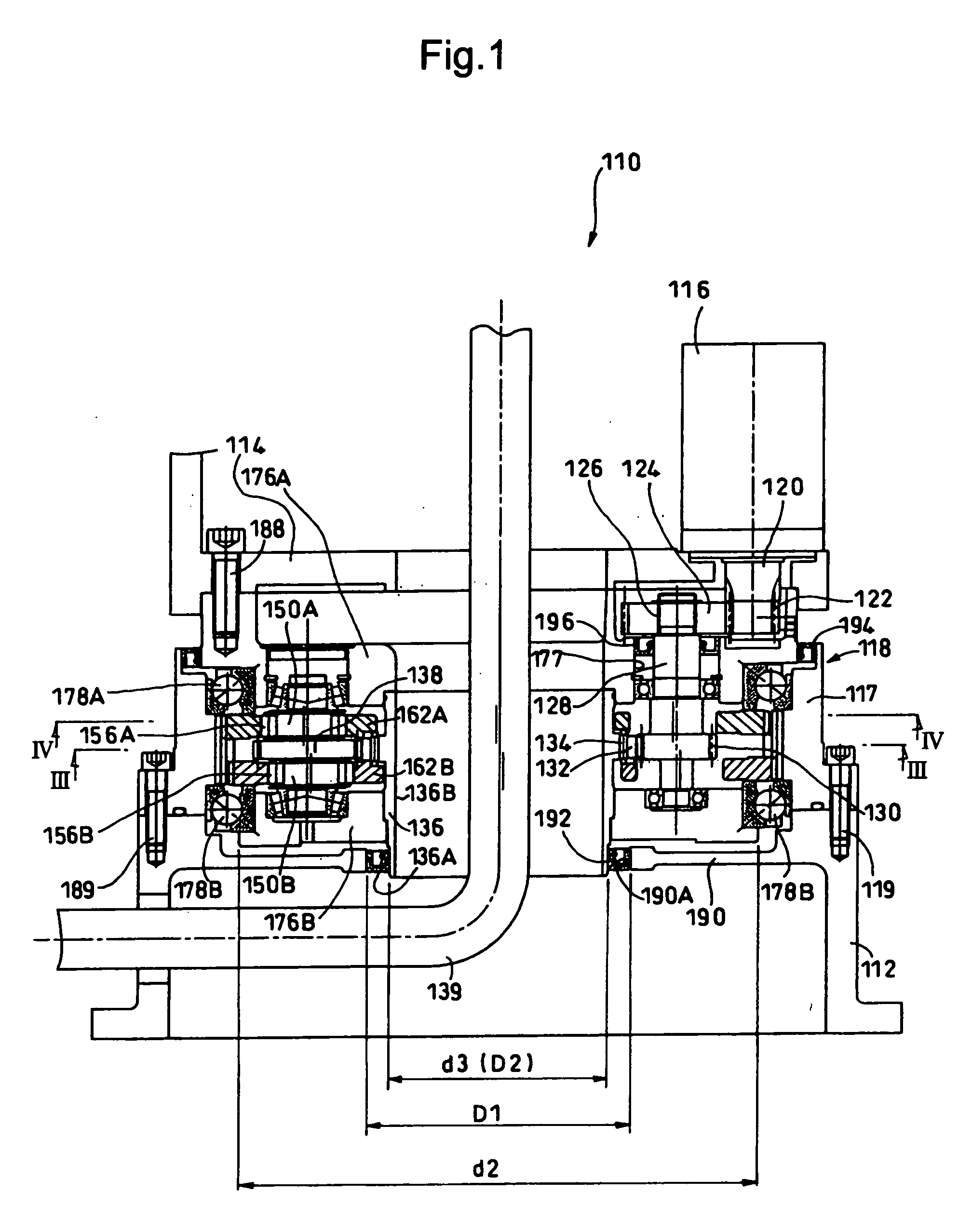
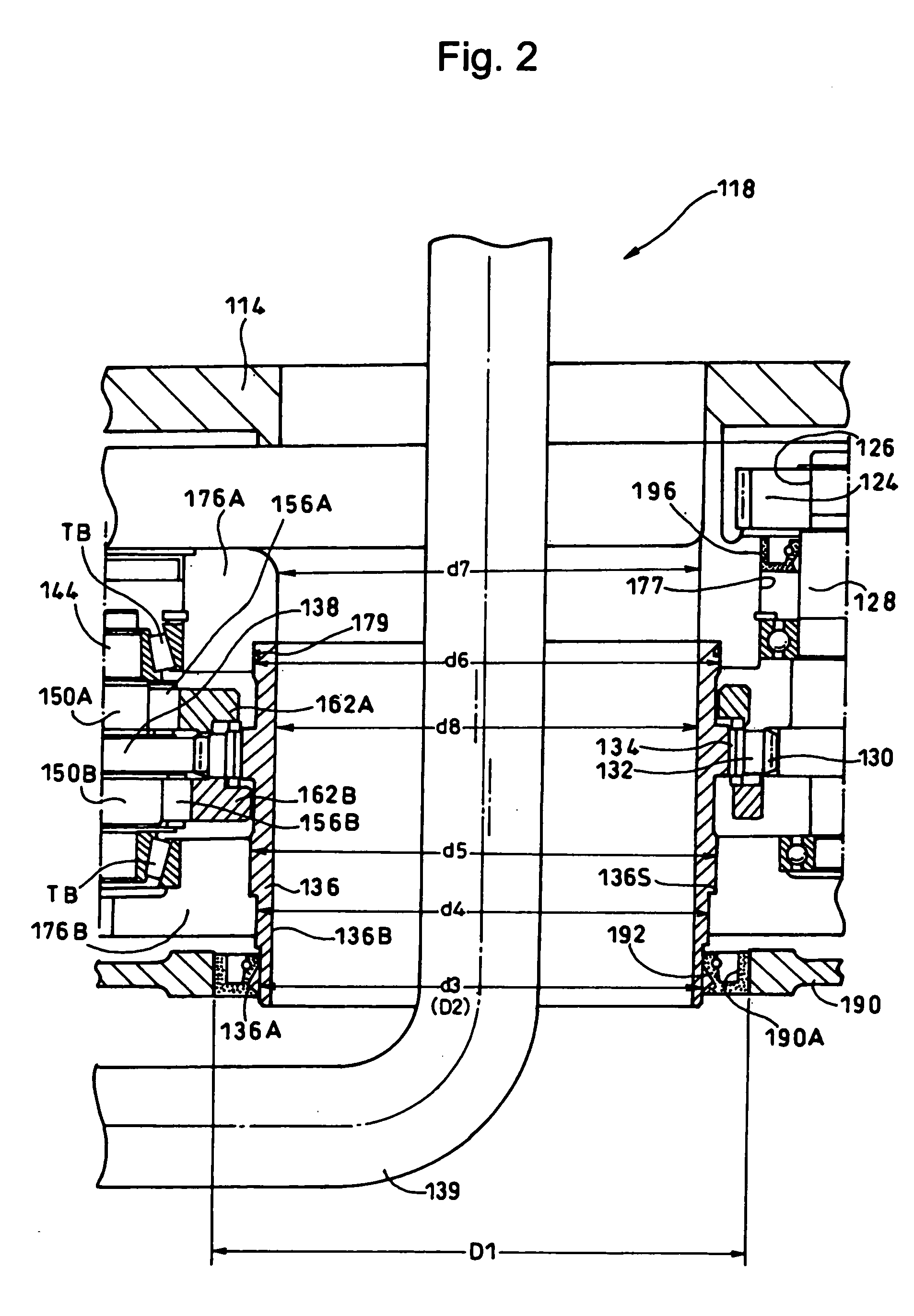
[0029]FIG. 1 is a sectional view of the joint driving apparatus for a robot according to an exemplary embodiment of the present invention. FIG. 2 is an enlarged sectional view of major parts in FIG. 1. Further, FIG. 3 and FIG. 4 are respectively the sectional views taken along lines III to III and IV to IV in FIG. 1.

[0030]The joint driving apparatus 110 comprises an oscillating internally meshing reduction mechanism 118. The (oscillating internally meshing) reduction mechanism 118 is fixed to a base (first member) 112 constituting a part of a fixing block of the robot (not illustrated), and rotatably supports and drives a movable member (a second member) 114 constituting another part of a movable bock of the robot.

[0031]Incidentally, when the joint driving apparatus is used for a joint driving after the second step of a robot, a base (first member) corresp...


PUM


Abstract

A joint driving apparatus for a robot comprises an oscillating internally meshing reduction mechanism, a center shaft member, a ring portion, and an oil seal disposed between the ring portion and the center shaft member. The oscillating internally meshing reduction mechanism is fixed to a first member and rotates the second member relatively with respect to the first member. An output member is arranged at the side of an external gear in an axial direction so as to output a relative rotation of an internal gear with the external gear. The center shaft member is fixed to the output member, and has a shaft portion extending up to the side opposite to the external gear in the axial direction of the output member. The ring portion is integrally formed with the first member and faces to the shaft portion of the center shaft member. The oil seal is disposed between the ring portion and the shaft portion.

Description

BACKGROUND OF THE INVENTION[0001]1. Field of the Invention[0002]The present invention relates to a joint driving apparatus for a robot.[0003]2. Description of the Related Art[0004]For example, International Publication No. WO2007 / 032400A1 has proposed an apparatus for driving joint portions of a robot. As shown in FIG. 6, the joint driving apparatus 10 is fixed to a base 12 constituting a part of a robot (not illustrated) and supports and drives a movable member 14 constituting another part of the robot so as to rotate freely.[0005]The joint driving apparatus 10 is equipped with a reduction mechanism 18 for reducing the rotation of a motor 16. A driving power of the motor 16 is transmitted in order of an input gear (not illustrated) mounted on a motor shaft 20, an external gear 22, one eccentric body shaft 24 (illustrated), and an eccentric body shaft gear 25 provided on the eccentric body shaft 24, and reaches a center gear 23. The center gear 23 is meshed with eccentric body shaft...

Claims


Application Information

Patent Timeline
Patent Type & Authority Applications(United States)
IPC IPC(8): F16H1/32B25J17/00
CPCF16H1/32B25J9/102F16H49/001Y10S901/19
Inventor TAMENAGA, JUN
Owner SUMITOMO HEAVY IND LTD
Why Eureka
Try Eureka