Wearable defibrillator with audio input/output

a technology of defibrillator and audio input, which is applied in the field of wearable defibrillators, can solve the problems of patients at risk of sudden death, patients at risk of tachyarrhythmia, and patients undergoing coronary artery occlusion and myocardial infarction, and patients placed at an inordinate risk

a technology of defibrillator and audio input, which is applied in the field of wearable defibrillators, can solve the problems of patients at risk of sudden death, patients at risk of tachyarrhythmia, and patients undergoing coronary artery occlusion and myocardial infarction, and patients placed at an inordinate risk

US20080306560A1Active Publication Date: 2008-12-11ZOLL MEDICAL CORPORATION

Image

  • Wearable defibrillator with audio input/output
  • Wearable defibrillator with audio input/output
  • Wearable defibrillator with audio input/output

Examples


Embodiment Construction

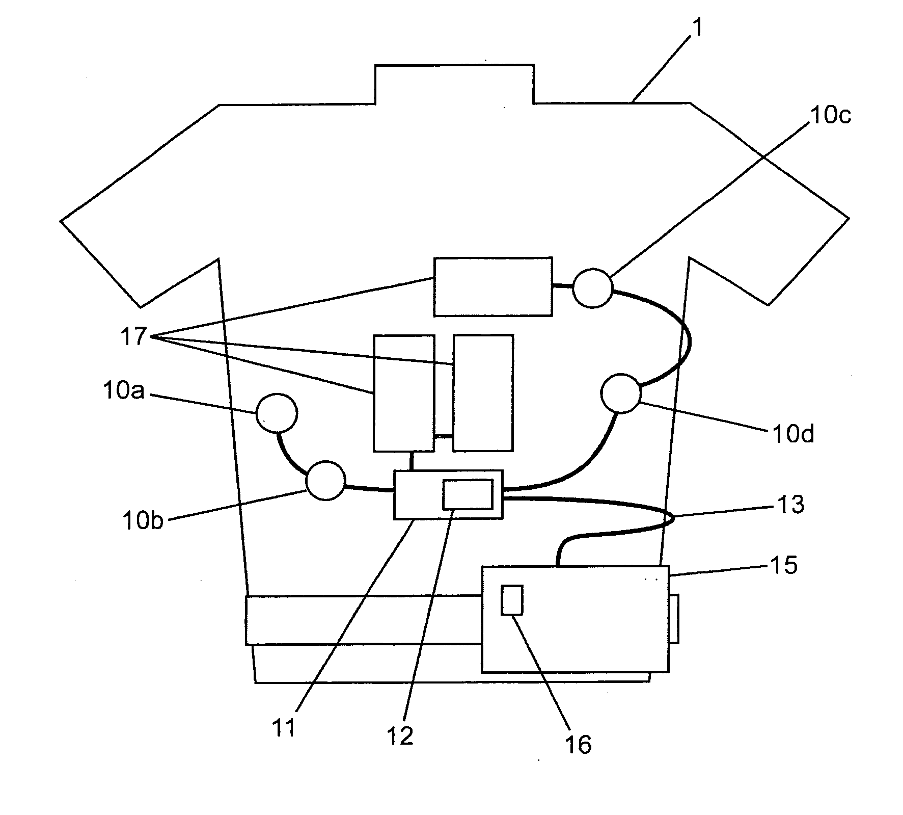
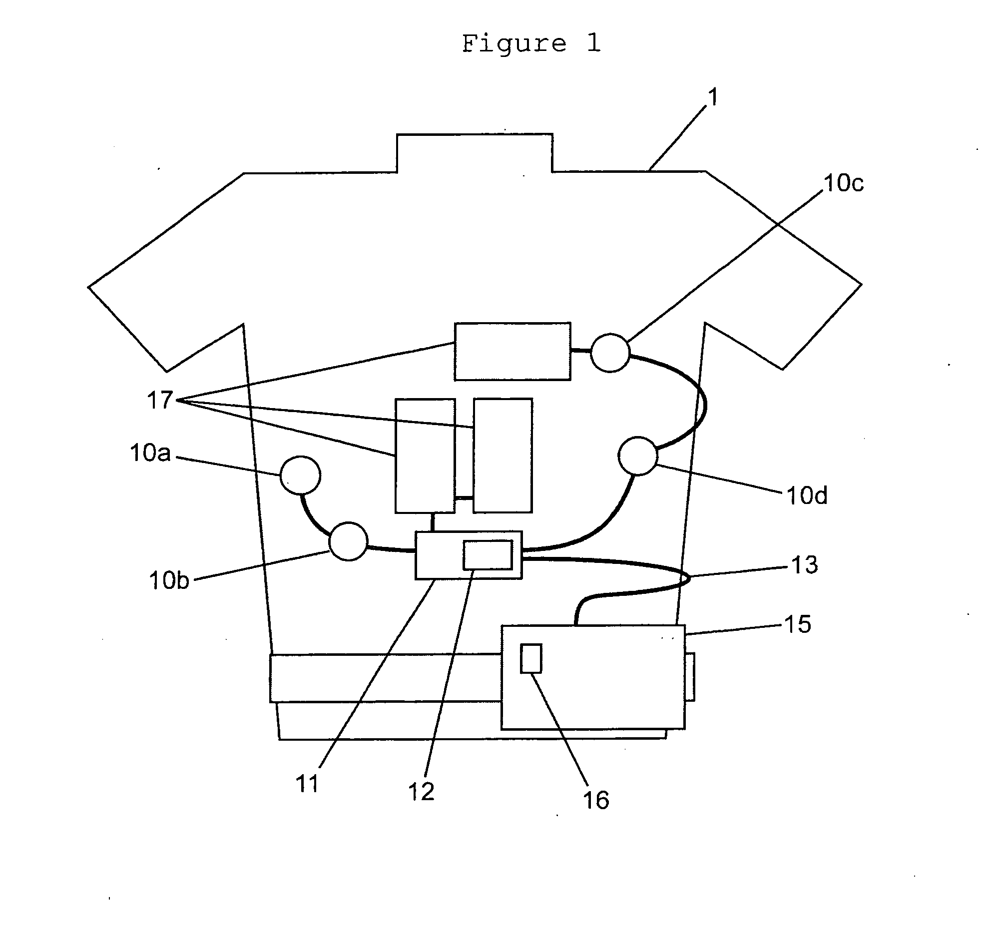
[0027]Referring to FIG. 1, a wearable defibrillator may be worn by a patient and may include a belt or harness or other apparel configured to permit the patient to wear the defibrillator. Sensors, such as electrodes 10a, 10b, 10c and 10d are removably attached to the patient when the wearable defibrillator is worn by the patient. The electrodes 10a, 10b, 10c and 10d form part of electrode assembly 11 and are operatively connected to a processing unit 15 via a trunk cable 13. In some embodiments, the processing unit 15 may include, without limitation, one or more processors, one or more controllers and / or one or more programs or other software stored in memory operatively connected to one or more processors.

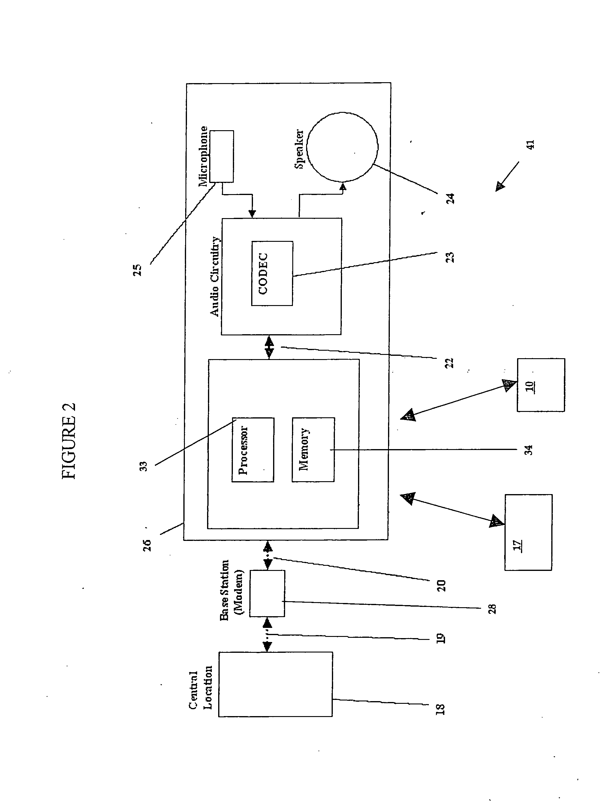
[0028]The processing unit 15 is operatively connected to therapy pads 17, at least one tactile stimulator 12, electrode assembly 11, and one or more audio devices 16. The audio devices 16 may include, for example, a microphone and a speaker. The therapy pads 17 are removably conne...


PUM


Abstract

A wearable defibrillator and method of monitoring the condition of a patient are disclosed. The wearable defibrillator includes at least one therapy pad, at least one sensor and at least one processing unit operatively connected to the one or more therapy pads and the one or more sensors. The wearable defibrillator also includes at least one audio device operatively connected to the one or more processing units. The one or more audio devices are configured to receive audio input from a patient.

Description

CROSS-REFERENCE TO RELATED APPLICATION[0001]The present application claims the benefit under 35 U.S.C. §119(e) of pending U.S. Provisional Patent Application Ser. No. 60 / 933,310 that was filed on Jun. 6, 2007. The entirety of U.S. Provisional Application Ser. No. 60 / 933,310 is incorporated herein by reference.FIELD OF THE INVENTION[0002]This invention relates to wearable defibrillators.BACKGROUND OF THE INVENTION[0003]There are many patients susceptible to heart arrhythmias who are at risk of sudden death. For example, patients undergoing a coronary artery occlusion and myocardial infarction are at substantial risk of tachyarrhythmia for several weeks following the coronary artery occlusion. Such patients are generally hospitalized but can be discharged earlier if there is a practical means to protect them from life threatening arrhythmias. One such practical means includes the implantation of an automatic defibrillator. However, patients may also be discharged prior to such an impl...

Claims


Application Information

Patent Timeline
11 Dec 2008
Publication
US20080306560A1
IPC
A61N1/39
CPC
A61N1/37217; A61N1/3925; A61N1/3993; A61N1/39; A61N1/046; A61N1/0484; A61N1/3904; A61B5/0002
Inventors
MACHO, JOHN D.; VOLPE, SHANE S.