
Clustering System and Flexible Interconnection Architecture Thereof

a computing system and clustering technology, applied in the field of clustering system and flexible interconnection architecture of computing system, can solve the problem that physical connection slots cannot be shared between one compute node and one storage devi

Inactive Publication Date: 2008-12-11
TYAN COMP
View PDF16 Cites 4 Cited by
  • Summary
  • Abstract
  • Description
  • Claims
  • Application Information

AI Technical Summary

Benefits of technology

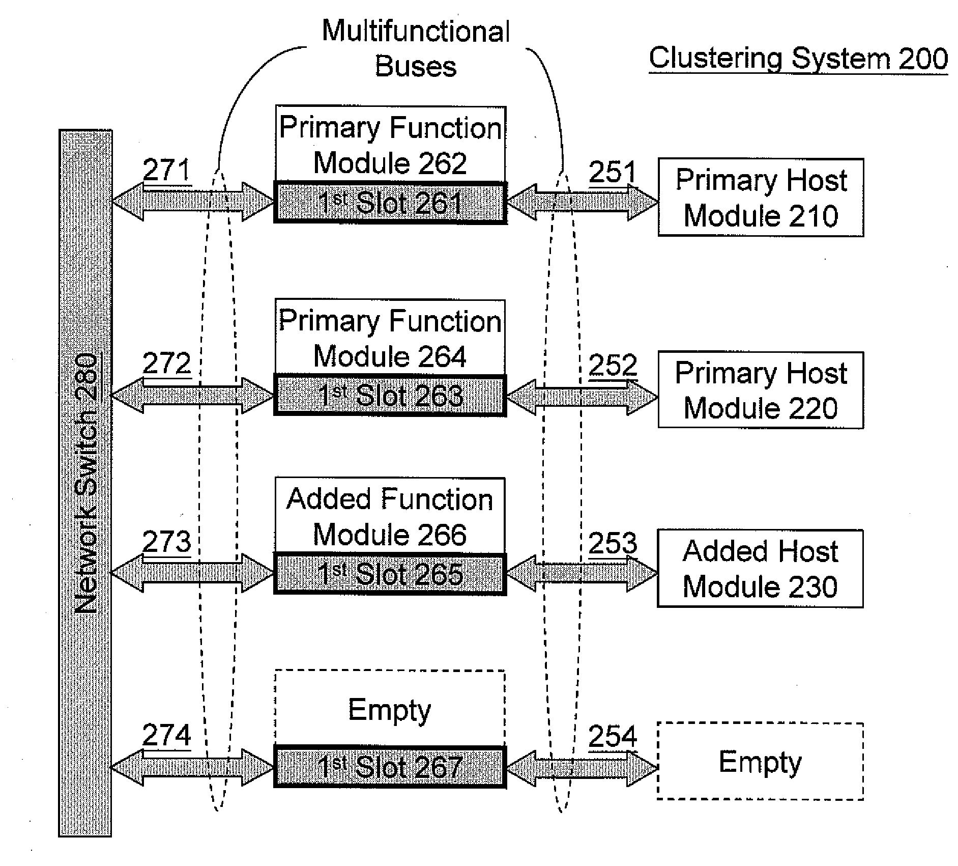
"The present invention provides a flexible system configuration for a clustering system by providing a slot for different types of functions, such as computation and storage. The interconnection architecture includes plural first slots, a primary function module, an added function module, and plural multifunctional buses. The primary host module and the added host module can be connected to the network switch through the first slots and the primary function module and the added function module can be connected to each other through the multifunctional buses. The system can be easily configured and can use different network technologies. The primary host module can be a compute node and the added host module can be a storage node. The multifunctional buses have one section protocol-compatible with the system input / output bus and another section physical-compatible with the physical network. The primary function module is a network interface controller module embedded with a network interface controller and the added function module is a passive through module to directly connect the multifunctional buses from the network switch and from the primary and / or added host module. The technical effects of the invention are a flexible system configuration and a convenient way to connect different host modules to a network switch."

Problems solved by technology

And these physical connection slots cannot be shared between one compute node and one storage device.

Method used


Image

  • Clustering System and Flexible Interconnection Architecture Thereof
  • Clustering System and Flexible Interconnection Architecture Thereof
  • Clustering System and Flexible Interconnection Architecture Thereof

Examples


Embodiment Construction

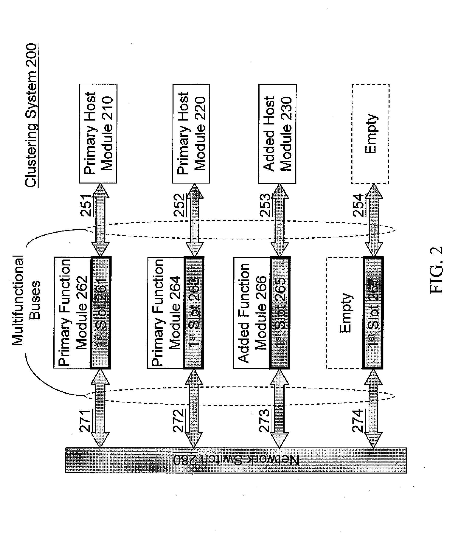
[0018]Please refer to FIG. 2. A flexible interconnection architecture for a clustering system 200 mainly includes one or more primary host modules 210 / 220, one or more added host modules 230, one or more first slots 261 / 263 / 265 / 267, one or more primary function modules 262 / 264, one or more added function modules 266, multifunctional buses 251 / 252 / 253 / 254, 271 / 272 / 273 / 274, and network switch 280.

[0019]Each primary host module 210 / 220 is basically a computer host with operating system in an operating system domain, such as a head node or compute node in a common clustering system. The added host module 230 provides network attached resources (such as storage spaces) that can be used by the primary host module 210 / 220 through the network switch 280.

[0020]Each primary function module 262 / 264 is to provide an interface, such as a NIC (Network Interface Controller) for the primary host module 210 / 220 to electrically connect with the network switch 280. Similarly, the added function module...


PUM


Abstract

An interconnection architecture is provided for flexibly connecting a primary host module or an added host module to a network switch in a clustering system. The interconnection architecture mainly includes plural first slots, a primary function module, an added function module and plural multifunctional buses. The first slots electrically connect the network switch with the primary and added host modules. The primary function module inserts in one of the first slots to electrically connect the primary host module with the network switch; and the added function module inserts in one of the first slots to electrically connect the added host module with the network switch. The multifunctional buses connect the network switch with the first slots and also connect the first slots with the primary host module and the added host module.

Description

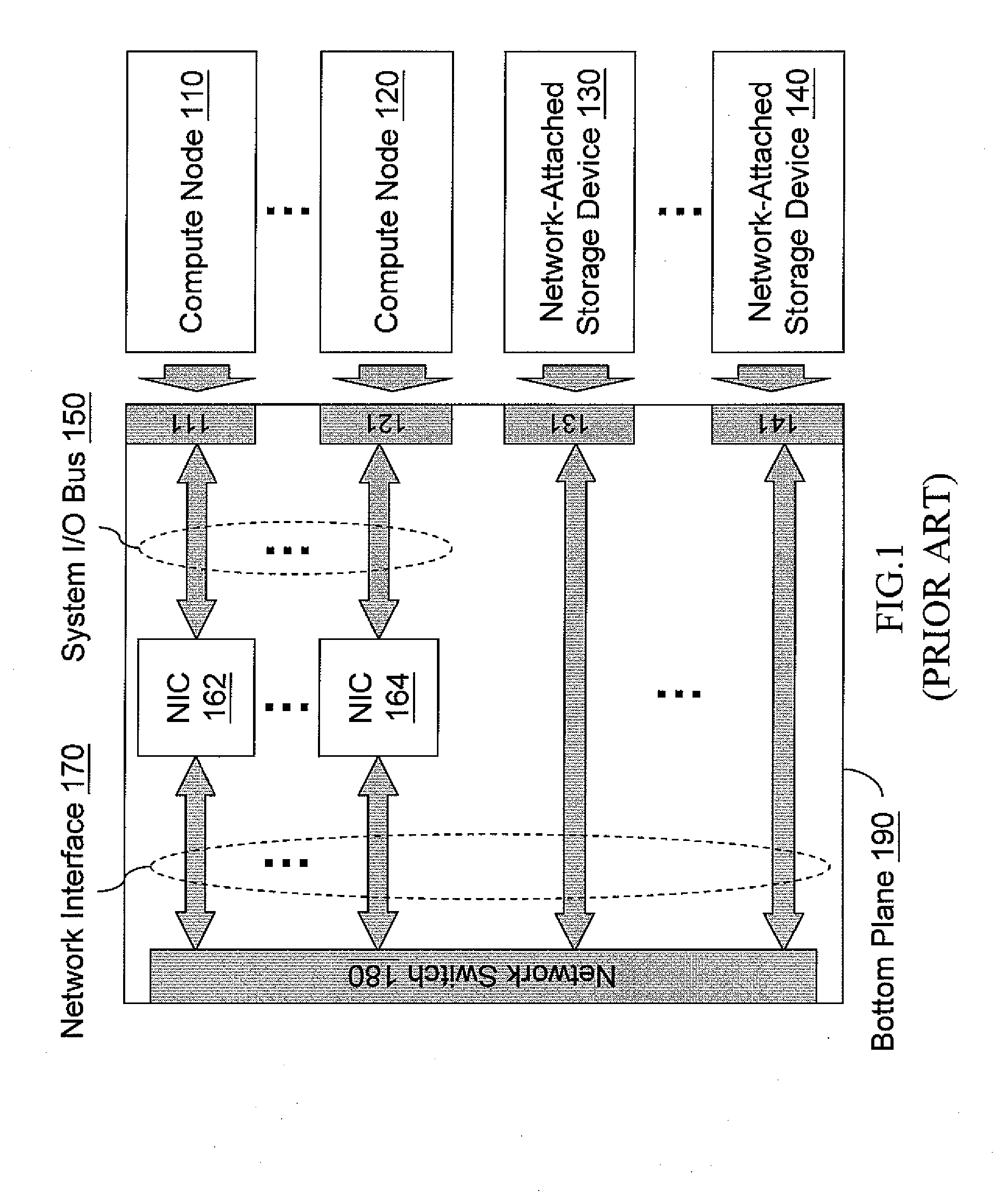
BACKGROUND OF THE INVENTION[0001]1. Field of Invention[0002]The present invention relates to an interconnection architecture of a computing system, and more particularly to multifunctional interconnections that facilitates multiple types of communication in a clustering system.[0003]2. Related Art[0004]Generally, in a typical clustering system, a connection slot for a specific module can only be used for similar function. For example, computation slot is dedicated for the use of computation, such as the use of connecting computation nodes; I / O (Input / Output) slot is only used for various I / O devices. To support different function, different dedicated slots need to be provided for those functions in the clustering system.[0005]FIG. 1 shows a typical implementation of a clustering computer in the prior art. The drawing specifically shows logical connections for computation and storage. The clustering system mainly includes compute nodes 110˜120, network-attached storage devices130˜140...

Claims


Application Information

Patent Timeline
Patent Type & Authority Applications(United States)
IPC IPC(8): G06F13/40
CPCG06F13/387
Inventor HIRAI, TOMONORIJONG, JYH MING
Owner TYAN COMP
Learn More