Micro-channel heat sink

a microchannel heat sink and heat sink technology, applied in the direction of basic electric elements, semiconductor devices, lighting and heating apparatus, etc., can solve the problem that the bubbles in the boiling fluid cannot easily flow backwards, and achieve high heat transfer capability, high power efficiency, and high stability

Inactive Publication Date: 2008-12-18
NATIONAL TSING HUA UNIVERSITY
View PDF10 Cites 12 Cited by
  • Summary
  • Abstract
  • Description
  • Claims
  • Application Information

AI Technical Summary

Benefits of technology

[0011]The present invention provides a micro-channel heat sink, whose miniaturized structure can prevent the reverse flow of bubbles and pressure oscillations. That is, the bubbles in the boiling fluid cannot easily flow backwards to block the transportation of a working fluid in micro-channels. Therefore, this micro-channel heat sink is a cooling device with high stability, high heat transfer capability, and high power efficiency.

Problems solved by technology

That is, the bubbles in the boiling fluid cannot easily flow backwards to block the transportation of a working fluid in micro-channels.

Method used


Image

  • Micro-channel heat sink
  • Micro-channel heat sink
  • Micro-channel heat sink

Examples


Embodiment Construction

[0019]The following will demonstrate the present invention using the accompanying drawings to clearly present the characteristics of the technology.

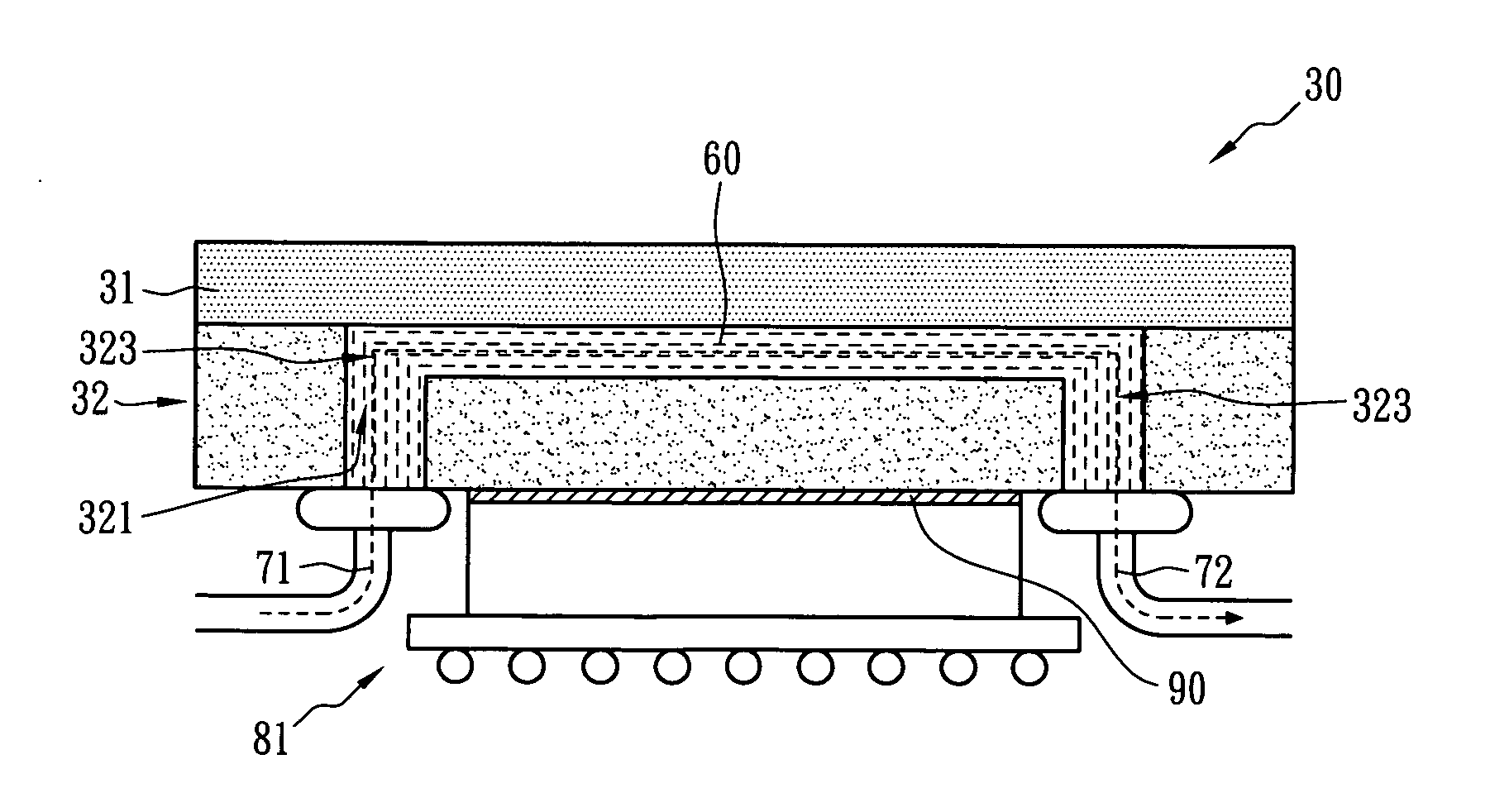
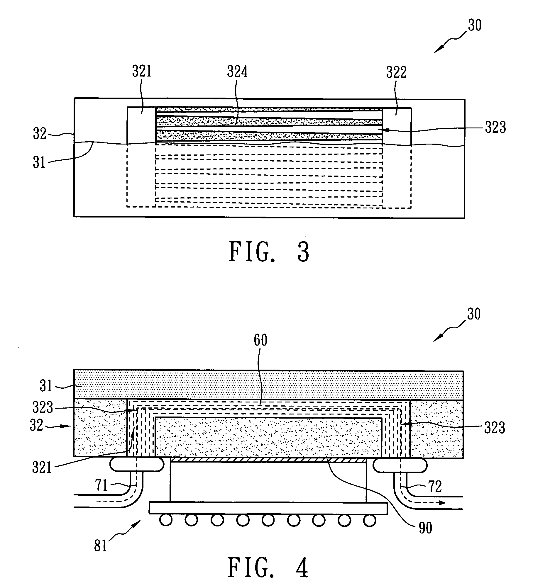
[0020]FIG. 3 is a top view showing a micro-channel heat sink in accordance with the present invention. The micro-channel heat sink 30 comprises an upper cover layer 31 and a cooling layer 32, wherein the cooling layer32 comprises at least one inlet fluid tank 321, a plurality of micro-channels 323, and at least one outlet fluid tank 322. The inlet fluid tank 321 can store and deliver the working fluids, and the outlet fluid tank 322 collects the heated working fluids flowing through the plurality of micro-channels. The plurality of micro-channels 323 is disposed between the inlet fluid tank 321 and the outlet fluid tank 322. The cross-sectional area of each of the micro-channels 323 gradually increases along the direction from the inlet fluid tank 321 towards the outlet fluid tank 322, and, conversely, the cross sectional area of the cha...


PUM


Abstract

A micro-channel heat sink comprises an upper cover layer and a cooling layer. The cooling layer comprises at least one inlet fluid tank, a plurality of micro-channels, and at least one outlet fluid tank. The inlet fluid tank can store and deliver the working fluids, and the outlet fluid tank collects the heated working fluid flowing through the plurality of micro-channels. The plurality of micro-channels are disposed between the inlet fluid tank and the outlet fluid tank, wherein the cross sectional area of each of the micro-channels increases along the direction towards the outlet fluid tank.

Description

BACKGROUND OF THE INVENTION[0001](A) Field of the Invention[0002]The present invention relates to a micro-channel heat sink, and more particularly, to a high performance micro-channel heat sink.[0003](B) Description of the Related Art[0004]With improvements in micro-scaling technologies for electrical components, various electronic products in recent years have been reduced in size to meet the specifications for portable design. The personal computer, digital camera, PDA, and mobile phone have attained the light weight and compact size required for portability. However, owing to the scaling of the electronic products in design, the issue of cooling for high performance electrical components has also arisen, and the industry has taken notice. Therefore, thermal analysis technologies have become a critical factor affecting how quickly products can be brought to market. According to reports by international electronics magazines, 50% of the causes of malfunctions in electronic products...

Claims


Application Information

Patent Timeline
Patent Type & Authority Applications(United States)
IPC IPC(8): F28D15/00
CPCF28F3/12H01L23/473H01L2224/73204H01L2924/15311H01L2924/1461H01L2924/00
Inventor PAN, CHINLI, PO CHANGLU, CHUN TINGLIN, KUN CHENG
Owner NATIONAL TSING HUA UNIVERSITY
Why Eureka
Try Eureka