
Motor controller

Inactive Publication Date: 2008-12-18
PANASONIC CORP
View PDF5 Cites 21 Cited by
  • Summary
  • Abstract
  • Description
  • Claims
  • Application Information

AI Technical Summary

Benefits of technology

[0016]With such a configuration, for example, even when a resonance frequency of the apparatus changes significantly in accordance with the load state, the notch control section controls the notch filter to change the notch width so as to attenuate a signal component of the original notch frequency and a signal component of the estimated oscillation frequency. Therefore, the motor controller of the present invention is capable of suppressing short-time oscillation, which occurs due to a significant change in resonance frequency of the apparatus, and is thus capable of constantly and stably controlling the motor.

Problems solved by technology

Therefore, in a case where a resonance frequency frequently changes due to a conditional change such as a positional change of the load, the oscillation and the notch frequency are modified every time a deviation occurs between the resonance frequency and the notch frequency, causing a problem of preventing smooth movement.

Method used


Image

  • Motor controller
  • Motor controller
  • Motor controller

Examples


first embodiment

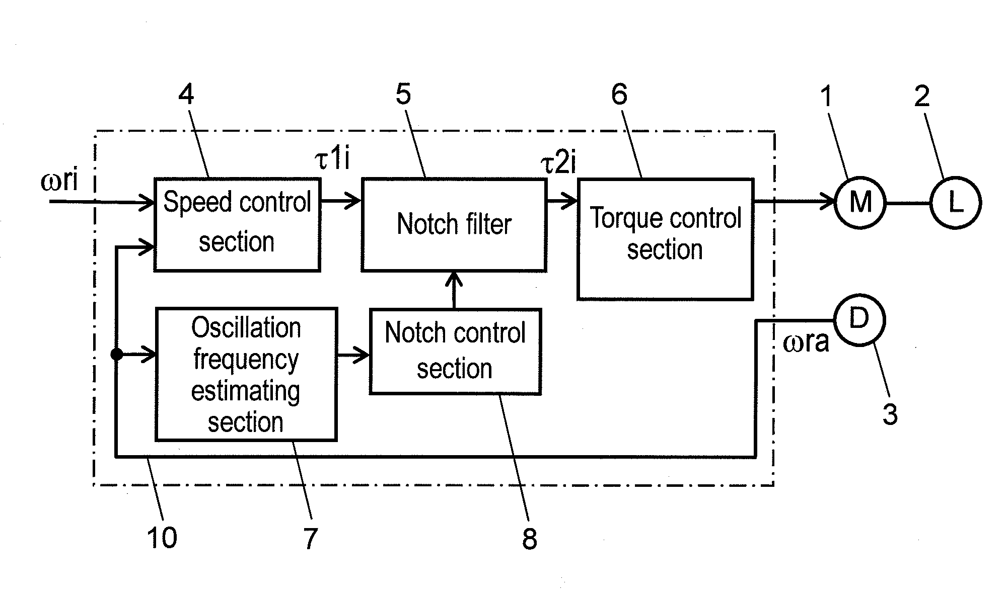
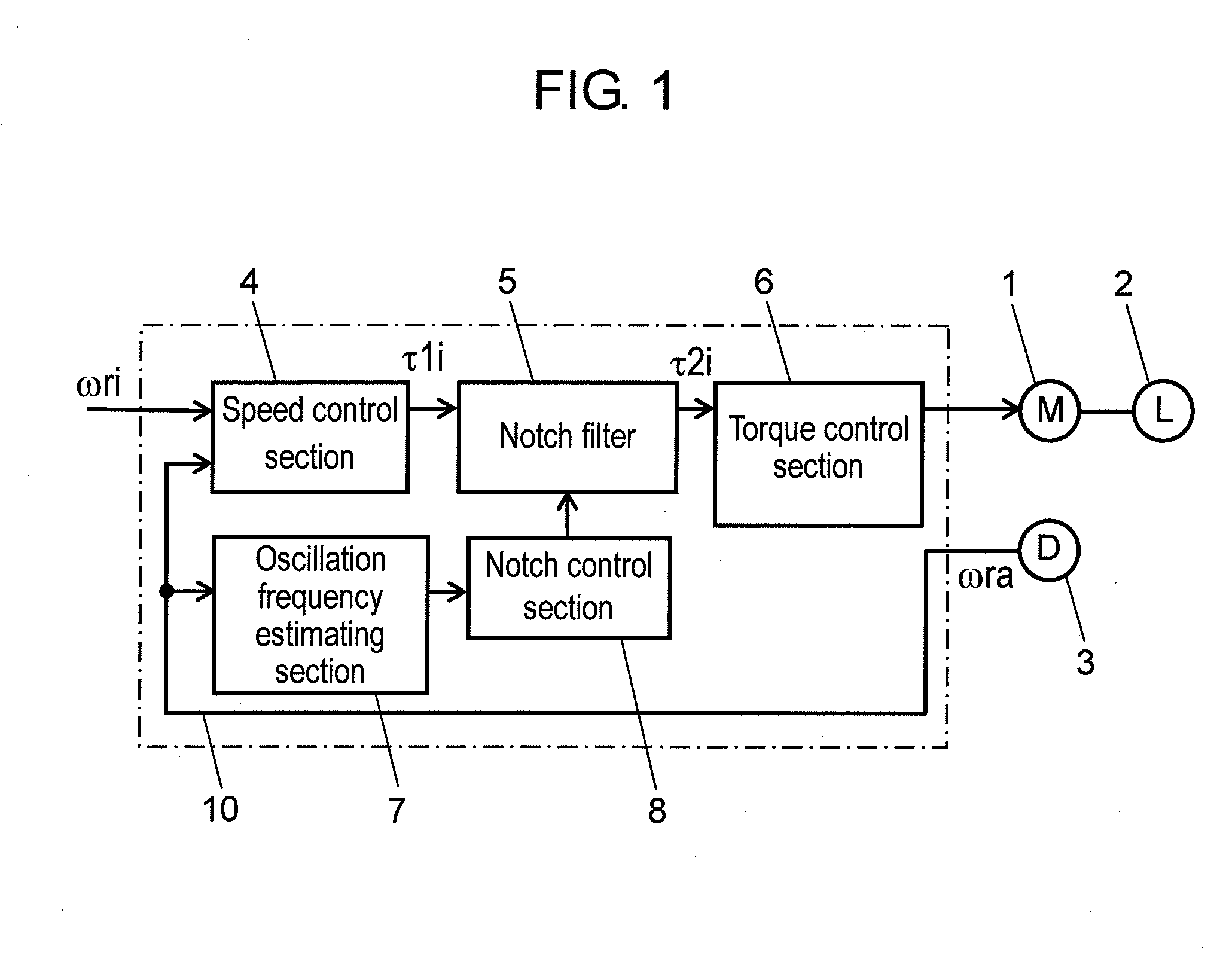
[0024]FIG. 1 is a block diagram of a motor controller according to a first embodiment of the present invention.

[0025]Motor controller 10 according to the first embodiment of the present invention is connected to motor 1 and speed detector 3. Motor 1 is connected with load 2. Further, speed detector 3 measures a rotational speed of a moving element (not shown) provided inside motor 1, and outputs speed detection signal ωra showing a speed amount in accordance with the rotational speed. It is to be noted that in the present embodiment, a description is given by taking an example of speed detector 3 detecting an amount of rotational speed of the moving element as a moving amount of moving section of motor 1 as described above.

[0026]As shown in FIG. 1, motor controller 10 includes speed control section 4, notch filter 5, oscillation frequency estimating section 7, notch control section 8, and torque control section 6.

[0027]Speed command signal ωri showing a speed command value and speed...

second embodiment

[0056]In the following, motor controller 20 according to a second embodiment of the present invention is described with reference to drawings.

[0057]FIG. 4 is a block diagram of motor controller 20 according to the second embodiment of the present invention.

[0058]In FIG. 4, the same constituents as those of motor controller 10 according to the first embodiment are provided with the same numerals, and detailed descriptions thereof are omitted.

[0059]In comparison with the first embodiment, motor controller 20 includes a plurality of notch filters 5, and also includes notch control section 80 that controls these notch filters 5. Notch control section 80 is capable of changing a notch frequency and a notch width of each of the plurality of notch filters 5. Further, notch control section 80 is capable of switching the state of the plurality of notch filters 5 between the valid state and the invalid state. It is to be noted that in the present embodiment, as shown in FIG. 4, a description ...


PUM


Abstract

A motor controller includes: a notch filter arranged inside a control system; an oscillation frequency estimating section which estimates an oscillation frequency component in a motor; and a notch control section which controls a notch filter so as to change a notch frequency and a notch width. The notch control section changes a frequency between an oscillation frequency and a notch frequency set in a notch filter as a new notch frequency, while changing a notch width to a new notch width such that the notch width is larger after the change than before the change.

Description

FIELD OF THE INVENTION[0001]The present invention relates to a motor controller for controlling a speed or a position of a motor as well as a load driven by the motor. The present invention particularly relates to a motor controller for suppressing mechanical resonance that occurs in the case of driving the load.BACKGROUND OF THE INVENTION[0002]Such a conventional motor controller for suppressing mechanical resonance is disclosed, for example, in Unexamined Japanese Patent Publication No. 2003-52188.[0003]In the following, the conventional motor controller is described with reference to FIG. 6. FIG. 6 is a block diagram showing a system configuration of the conventional motor controller.[0004]This conventional motor controller 100 is connected to motor 101 and speed detector 103. Motor 101 is connected with load 102. Further, speed detector 103 measures a speed of motor 101, and outputs speed detection signal ωra of motor 101.[0005]As shown in FIG. 6, motor controller 100 includes s...

Claims


Application Information

Patent Timeline
IPC IPC(8): H02P23/04G05B13/02H02P25/098H02P29/00
CPCH02P23/04
Inventor TAZAWA, TORU
Owner PANASONIC CORP
Learn More