
Image outputting apparatus and program

a technology of image printing and output apparatus, which is applied in the field of image printing apparatus and program, can solve the problems of limiting the position of people, image printing in such a format as disclosed in jpn. pat. appln. no. 7, 234460, and may not be well observed

Inactive Publication Date: 2008-12-18
OLYMPUS IMAGING CORP +2
View PDF6 Cites 36 Cited by
  • Summary
  • Abstract
  • Description
  • Claims
  • Application Information

AI Technical Summary

Benefits of technology

[0009]According to a first aspect of the invention, there is provided an image outputting apparatus for displaying images of a 3D image file composed of stereoscopic image data which represents a plurality of monocular images constituting a multi-ocular stereoscopic image and information which is added to the stereoscopic image data and which indicates that the data is stereoscopic data, the apparatus comprising: a display output mode switching unit whic

Problems solved by technology

Particularly, the direct-view display limits positions where people can observe images.
However, any image printed in such a format as disclosed in Jpn. Pat. Appln. No. 7-234460 may look unnatural or cannot be well observed, because it consists of left monocular image stripes and right monocular image stripes that are alternately arranged.

Method used


Image

  • Image outputting apparatus and program
  • Image outputting apparatus and program
  • Image outputting apparatus and program

Examples


first embodiment

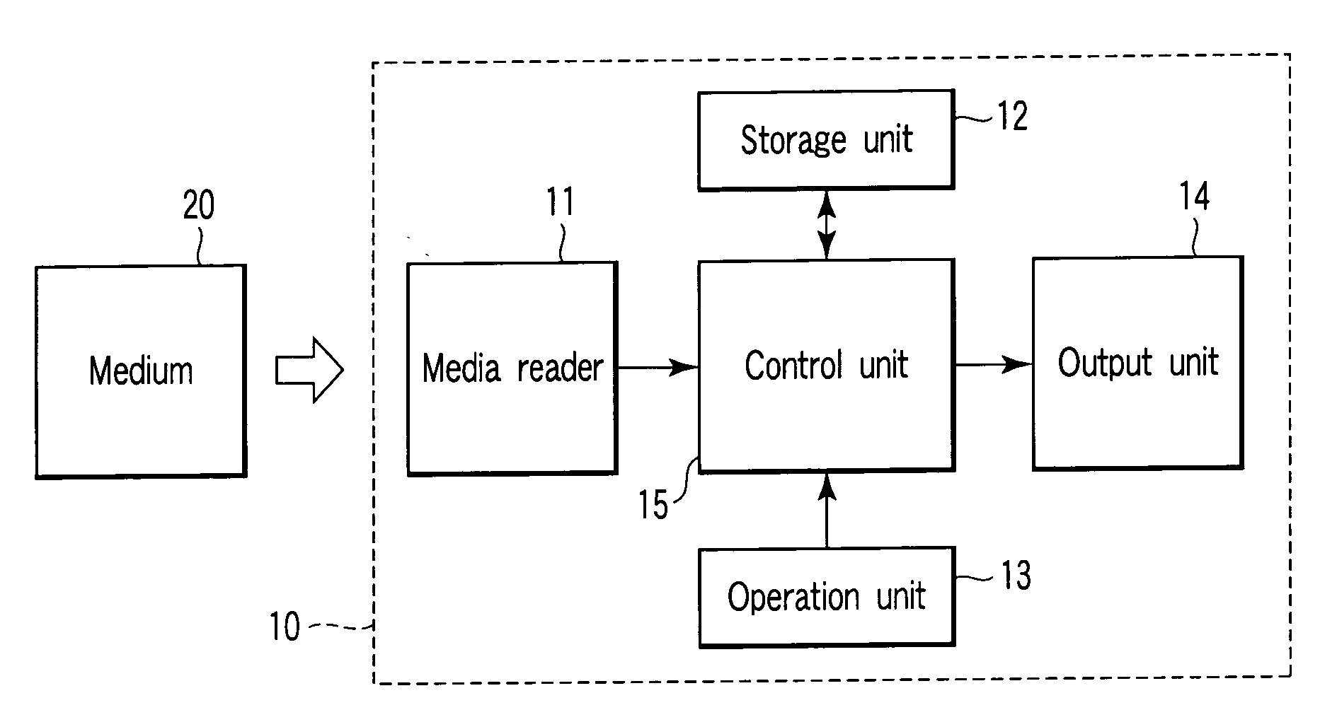
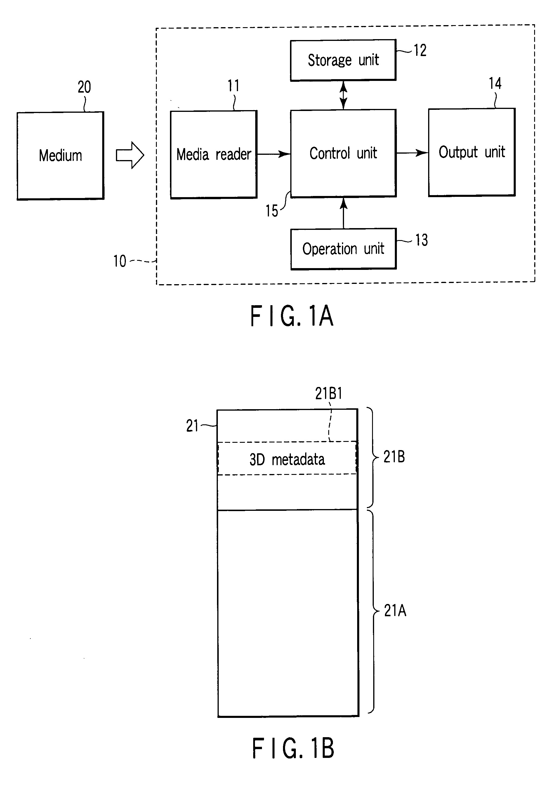
[0028]FIG. 1A is a diagram showing the configuration of an image outputting apparatus 10 according to a first embodiment of this invention. The image outputting apparatus 10 comprises a media reader 11, a storage unit 12, an operation unit 13, an output unit 14, and a control unit 15. The media reader 11 is designed to read image files from a medium 20. The storage unit 12 stores programs and various data items. The operation unit 13 inputs instructions when operated by a user. The output unit 14 is, for example, a 3D liquid crystal display that displays images based on image files. The control unit 15 is constituted by a CPU that controls the other components of the image outputting apparatus 10.

[0029]The image outputting apparatus 10 may be provided in the form of a standalone display apparatus that comprises the above-described configuration and a housing containing the configuration. For example, the storage unit 12 and the control unit 15 are implemented as a personal computer,...

second embodiment

[0053]In the first embodiment, the output unit 14 is a display that can display 3D images. In an image outputting apparatus 10 according to a second embodiment, the output unit 14 is a printer that can print images of 3D image files.

[0054]FIG. 3A is a diagram showing the configuration of the image outputting apparatus 10 according to the second embodiment of the present invention. This apparatus 10 has a display unit 16, in addition to the components the first embodiment has. The display unit 16 is configured to display inquiry messages to the user and the operating mode of the image outputting apparatus 10. As indicated above, the output unit 14 is a printer. Like the first embodiment, the image outputting apparatus 10 can be provided as a stand-alone printing apparatus that comprises the above-described configuration and a housing containing the configuration. Alternatively, it may comprise a PC. Further, the apparatus 10 may have a network connection unit in place of the media re...


PUM


Abstract

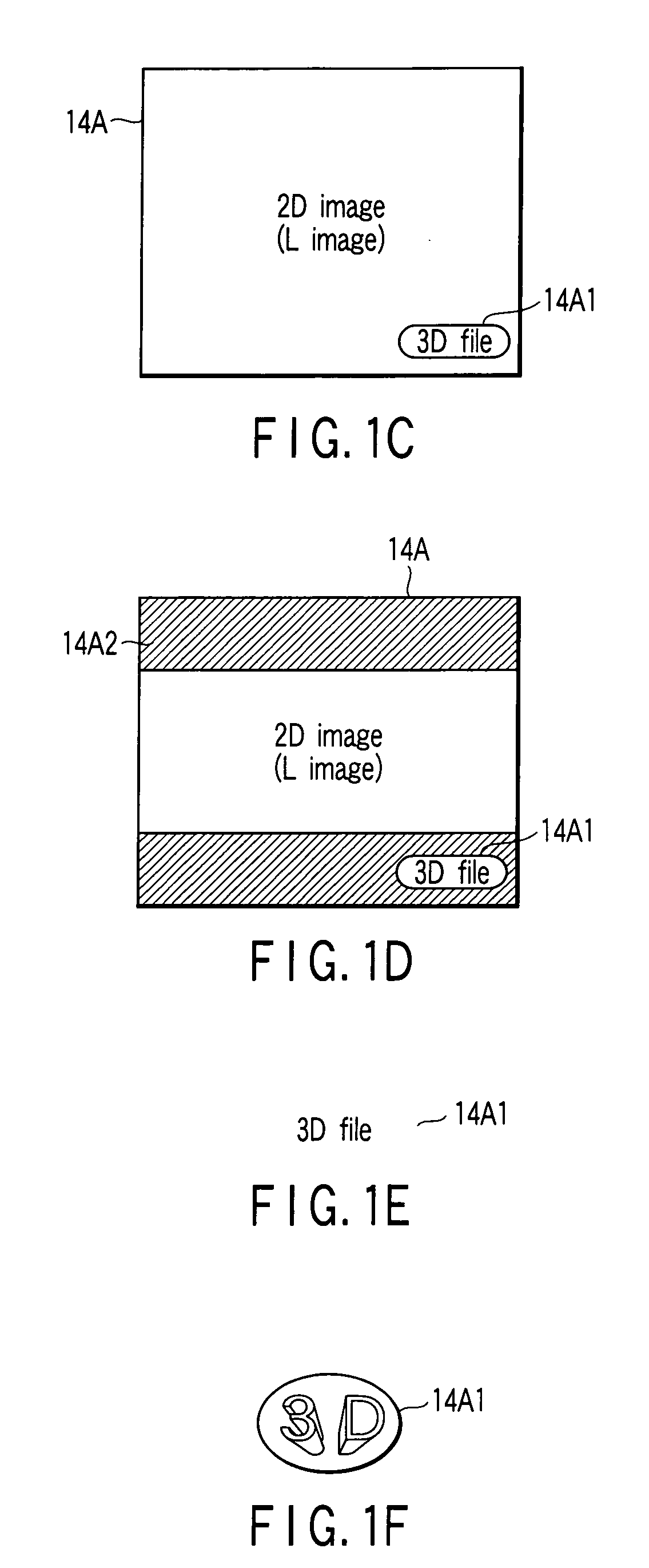
An operation unit switches the operating mode between a 3D display output mode in which the images of the 3D image file are displayed as a stereoscopic images and a 2D display output mode in which one of the images of the 3D image file is displayed as an ordinary planar image. The 3D image file is composed of stereoscopic image data which represents a plurality of monocular images constituting a multi-ocular stereoscopic image and information which is added to the stereoscopic image data and which indicates that the data is stereoscopic data. In the 2D display output mode, a control unit makes an output unit display an image of the 3D image file read from a medium by a media reader and also display a mark on the same screen, indicating that the image displayed in the 2D display output mode is based on the 3D image file.

Description

CROSS REFERENCE TO RELATED APPLICATIONS[0001]This is a Continuation Application of PCT Application No. PCT / JP2006 / 314276, filed Jul. 19, 2006, which was published under PCT Article 21(2) in Japanese.[0002]This application is based upon and claims the benefit of priority from prior Japanese Patent Application No. 2005-208707, filed Jul. 19, 2005, the entire contents of which are incorporated herein by reference.BACKGROUND OF THE INVENTION[0003]1. Field of the Invention[0004]The present invention relates to an image outputting apparatus that displays or prints images of a 3D image file. The invention also relates to a program that enables computers to function as such an image outputting apparatus.[0005]2. Description of the Related Art[0006]A direct-view display using 3D liquid crystal (see, for example, Jpn. Pat. Appln. No. 5-122733), a face-mount display (FMD) capable of displaying 3D images, or a head-mount display (HMD) capable of displaying 3D images can display images of a 3D i...

Claims


Application Information

Patent Timeline
IPC IPC(8): H04N13/04
CPCH04N13/0066H04N13/007H04N19/597H04N13/0454H04N13/0497H04N13/0409H04N13/183H04N13/31H04N13/359H04N13/178H04N13/398H04N1/00G06T15/00
Inventor YOSHIDA, HIDEAKIMASHITANI, KENNOMURA, TOSHIOUCHIUMI, TADASHISEKIZAWA, HIDEHIKO
Owner OLYMPUS IMAGING CORP
Learn More