Image Coding, Recording and Reading Apparatus

a technology of image coding and recording, applied in the direction of signal generator with optical-mechanical scanning, color television with bandwidth reduction, signal generator, etc., can solve the problems of small utilization factor of coding units and no function of improving image quality, and achieve the effect of preserving the image quality of output and increasing the amount of information of decoded original images

Inactive Publication Date: 2008-12-18
MITSUBISHI ELECTRIC CORP
View PDF0 Cites 36 Cited by
  • Summary
  • Abstract
  • Description
  • Claims
  • Application Information

AI Technical Summary

Benefits of technology

[0008]Therefore, at the time of coding the inputted original image, the apparatus generates and codes the difference image of the original image, records the coded streams of both of the images generated thereby, and, at the time of a playback, augments the amount of information of the decoded original image with the decoded difference image acquired by decoding the difference image. As a result, the image quality of the output is maintained at a high level. When the present invention is applied to an image coding, recording and reading apparatus which is so constructed as to record two or more programs simultaneously, coding units and decoding units which are placed in a non-use state when the apparatus records only one program can be used effectively.

Problems solved by technology

A problem with prior art image coding, recording and reading apparatus constructed as mentioned above is that they do not have any function of improving the image quality of a coded stream according to its use when coding the coded stream again.
A problem with image coding, recording and reading apparatus which can record two or more programs simultaneously is that when recording only one program, other coding units are not used and the utilization factor of the coding units is small.

Method used


Image

  • Image Coding, Recording and Reading Apparatus
  • Image Coding, Recording and Reading Apparatus
  • Image Coding, Recording and Reading Apparatus

Examples


embodiment 1

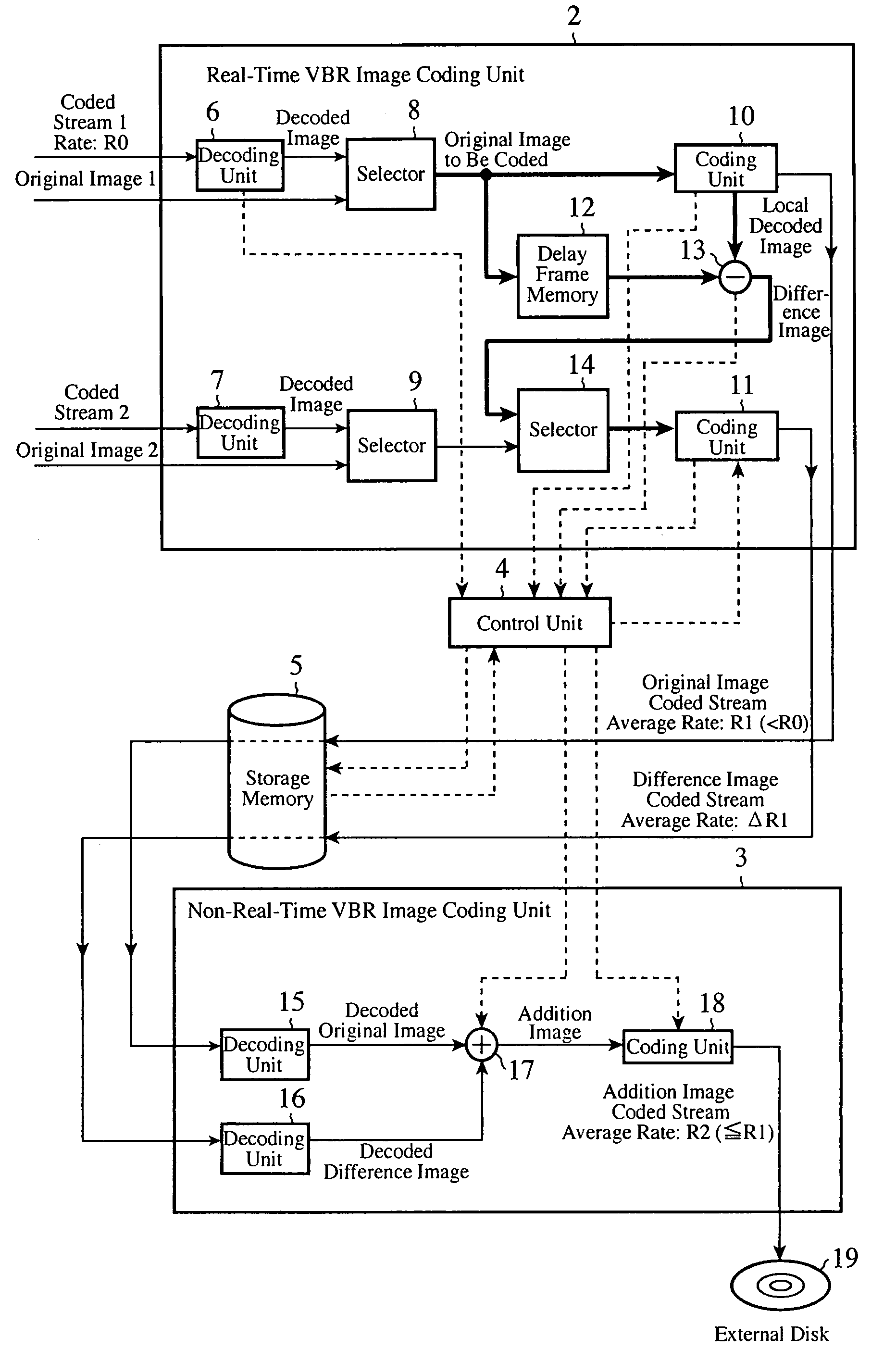
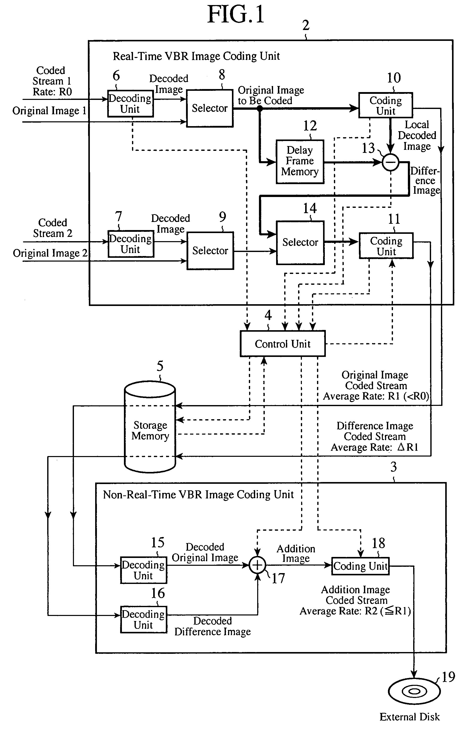
[0035]FIG. 1 is a block diagram showing the structure of an image coding, recording and reading apparatus in accordance with embodiment 1 of the present invention. The image coding, recording and reading apparatus shown in FIG. 1 has a structure of coding contents data about different images inputted simultaneously thereto so as to generate coded streams, recording them into an identical storage memory, and recording one of the coded streams which is selected from the storage memory into a record external disk. In this embodiment 1, an explanation of an application of the image coding, recording and reading apparatus will be made by focusing on a process of recording only one program into a storage memory and a process of reading a program from a storage memory.

[0036]This image coding, recording and reading apparatus is provided with a real-time VBR (Variable Bit Rate) image coding unit (i.e., an image coding means) 2, a non-real-time VBR image coding unit 3, a control unit 4, and a...

embodiment 2

[0062]FIG. 10 is a block diagram showing the structure of an image coding, recording and reading apparatus in accordance with embodiment 2 of the present invention.

[0063]The image coding, recording and reading apparatus is provided with a real-time VBR image coding unit 41, a non-real-time VBR image coding unit 42, a control unit 43, and a storage memory 44.

[0064]In the structure of the real-time VBR image coding unit 41, decoding units 45, 46, and 47 are means for, when inputs to the image coding, recording and reading apparatus are coded streams, decoding them, respectively. Selectors 48, 49, and 50 are means for selecting either decoded images decoded by the decoding units 45, 46, and 47 or the original image, respectively. Selectors 51 and 52 are means for selecting either the output of the selector 48, or the outputs of the selectors 49 and 50, respectively. Coding units 53, 54, and 55 are means for coding the original images to be coded which are inputted thereto simultaneousl...

embodiment 3

[0075]FIG. 12 is a block diagram showing the structure of an image coding, recording and reading apparatus in accordance with embodiment 3 of the present invention.

[0076]The image coding, recording and reading apparatus is provided with decoding units 61, 62, and 63, selectors 64 to 68 and 74, coding units 69, 70, and 71, a control unit 72, and a storage memory 73. The decoding units 61, 62, and 63 are means for, when inputs to the image coding, recording and reading apparatus are coded streams, decoding them. The selectors 64, 65, and 66 are means for selecting either decoded images generated by the decoding units 61, 62, and 63 or the original image, respectively. The selector 67 is a means for selecting either the output of the selector 64 or the output of the selector 65. The selector 68 is a means for selecting either the output of the selector 64 or the output of the selector 66. The coding units 69, 70, and 71 are means for coding one inputted original image to be coded accor...


PUM


Abstract

An image coding, recording and reading apparatus generates a local decoded image which is used for motion compensation prediction at the same time when coding an original image to be coded so as to generate an original image coded stream, acquires a difference image which is a difference between the local decoded image and the original image to be coded, codes the difference image so as to generate a difference image coded stream, records the original image coded stream and the difference image stream generated thereby into a storage memory, and adds an original image and a difference image which are obtained by decoding both the above-mentioned coded streams read out of the storage memory, respectively, so as to generate an addition image.

Description

FIELD OF THE INVENTION[0001]The present invention relates to an image coding, recording and reading apparatus which codes image data, such as image data about a broadcast program, records the coded image data thereinto, and outputs the recorded coded stream at a coding rate depending upon (or suiting) its use.BACKGROUND OF THE INVENTION[0002]Generally, a method of temporarily recording contents data containing an image and a sound into a predetermined memory after creating them, and reading and using them when a request to read and use them is made. When recording contents data into the memory, they are coded to compress the amount of information of the contents data with the input / output rate of the memory being reduced to a low one. As uses of the coded contents data which are thus recorded and stored, there are a record of them into another recording media, such as a DVD, broadcasting, and a stream distribution via a transmission line. Therefore, there is a demand to suit one con...

Claims


Application Information

Patent Timeline
Patent Type & Authority Applications(United States)
IPC IPC(8): H04N7/26
CPCH04N9/8042H04N9/8227H04N19/119H04N19/172H04N19/61H04N19/86H04N19/132H04N19/146H04N19/154H04N19/17H04N19/82H04N19/117
Inventor HIWASA, NORIMICHIINOMATA, HIDEKISAKATE, HIROHARUNEMOTO, AYAKO
Owner MITSUBISHI ELECTRIC CORP
Why Eureka
Try Eureka