
Carbon hydrostatic face seal

a hydrostatic face and carbon technology, applied in the direction of machines/engines, liquid fuel engines, mechanical equipment, etc., can solve the problems of increasing fuel consumption, reducing engine efficiency, and significantly diminishing the functionality of the engine itsel

Active Publication Date: 2008-12-18
STEIN SEAL
View PDF3 Cites 27 Cited by
  • Summary
  • Abstract
  • Description
  • Claims
  • Application Information

AI Technical Summary

Benefits of technology

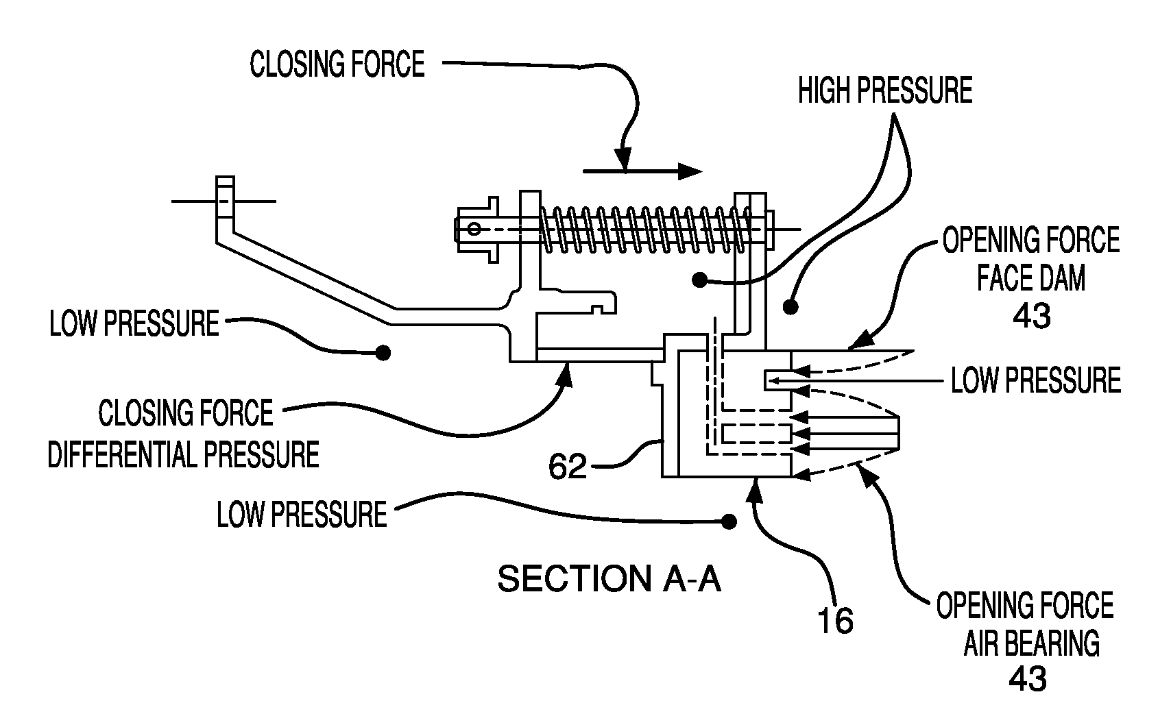
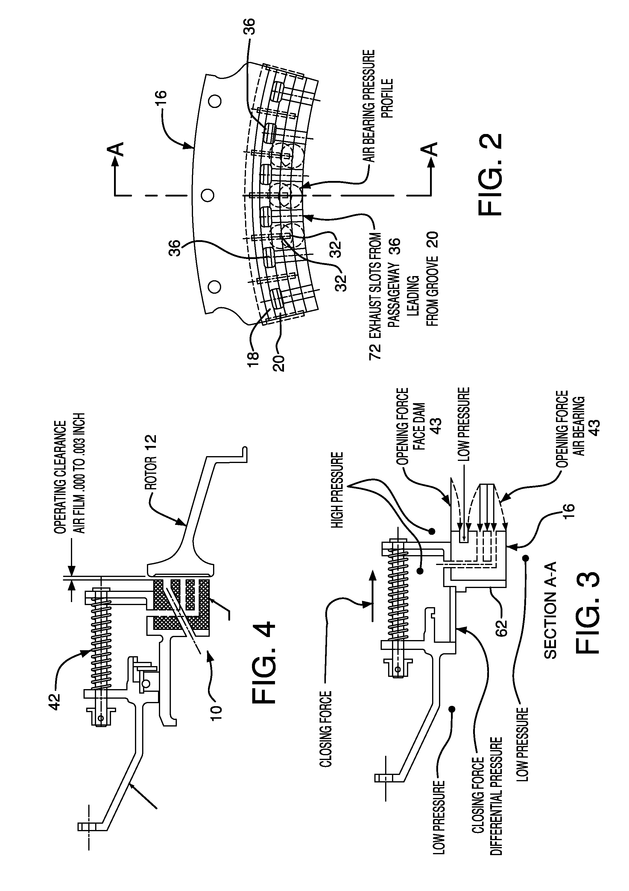
[0010]In one of its aspects, the present invention provides a force balanced seal for use in connection with a rotor in a turbomachine. The seal includes a sealing member in opposed facing disposition to the rotor. The member has a face dam portion having a surface parallel to a sealing surface of the rotor, a groove facing the rotor and bounding the face dam surface, and an air bearing surface facing the sealing surface of the rotor. A second passageway extends through the sealing member from the air bearing surface to a radially outwardly facing surface of the member. A first passageway also extends through the sealing member from the groove to a member surface facing oppositely from the air bearing surface. The seal further includes a housing means connected to a stationary part of the turbomachine for biasing the member towards the rotor. The combination of the bias and the pressure difference as between high pressure and low pressure regions on either side of the seal, when applied to the member in a direction towards the rotor, is sufficiently balanced by the combination of high pressure applied to the face dam and force resulting from outward flow of high pressure air exhausting from the second passageway in the air bearing surface, to maintain operating clearance between the member and the rotor.

Problems solved by technology

If air is allowed to leak across these seals, this may significantly diminish the functionality of engine itself.
For example, air leakage can lead to increase fuel consumption, reduce engine efficiency, and increase maintenance costs by increasing turbine inlet temperatures.
Additionally, leakage of liquids into a high pressure compartment of a turbine engine also affects performance of the equipment where the seal is used.
Specifically, lubricant leakage during static or dynamic situations can lead to oil coking, engine fire or the production of noxious odor therefrom.
However, the minimum radial clearance is limited by manufacturing tolerances, rotor concentricity control, and thermal growth between rotating and stationary components.
If the radial clearance is too small, this results in premature seal wear and possible engine damage.
Conversely, if the radial clearance is too large, this results in excess leakage.
First, the disclosed seal does not include a means for maintaining the ring member concentric with respect to the axis of the engine or with other seal components.
To this end, the seal is imbalanced and does not create an effective seal.
Rings pressurized radially inwardly will deform to an out-of-round shape with reduced sealing capability unless they are sufficiently massive and stiff.
Third, differential thermal growth and other effects influencing the clearance between the seal housing and face seal ring member can result in changes in pressure forces acting on seal components, which can result in poor sealing.
Fourth, the seal as disclosed includes an auxiliary restrictor tooth integral with or mounted on the ring member, which adds weight to the ring member, and increases pressure closing forces on the ring member, with the result that heavy spring means must be used to bias the ring member away from the sealing surface.
Finally, the seal does not efficiently vent air exiting the air bearing space and the restrictor tooth to the low pressure region.
However, in a static state there is no seal between the high pressure compartment and low pressure compartment.
Accordingly, there is no seal to prevent any lubricant, such as oil, that may be contained within the low pressure compartment from leaking into the high pressure compartment.
Leakage of liquids into the high pressure compartment adversely affects performance of the equipment where the seal is used.
In case of an aircraft engines, oil leakage across the seal into a hot air side may cause oil coking or an engine fire.
When an oil lubricant is used, mixing the oil with the gas could result in formation of oil coke, a byproduct of oil heated to an elevated temperature, which chemically alters the oil and is detrimental to the gas turbine.
Oil coke can foul seal surfaces reducing the integrity of the seal and prevent proper bearing lubrication within the lubricant sump.
Finally, oil coking often leads to a noxious odor that may flow into a passenger space of the vehicle.
This odor can be unpleasant and alarming to passengers unaware of the source of the smell.

Method used


Image

  • Carbon hydrostatic face seal
  • Carbon hydrostatic face seal
  • Carbon hydrostatic face seal

Examples


Embodiment Construction

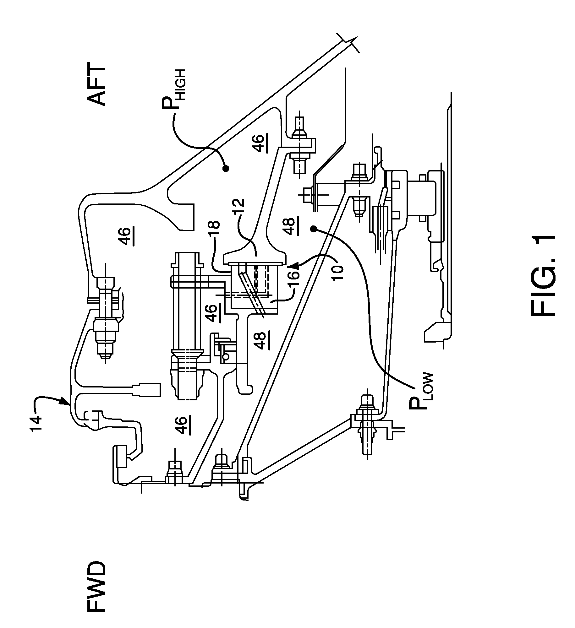
[0024]Referring to FIG. 1, a segment of a gas turbine engine, designated generally as 14, is illustrated. More specifically, a force balanced seal, according to the present invention, is illustrated and may be considered to include a rotor, designated generally 12, which forms a part of the gas turbine engine, and a sealing assembly, designated generally as 10. The sealing assembly, discussed herein, is provided as a sealing means respecting and sometimes against the rotor 12 by a stationary annular carbon graphite member 16. To this end, the sealing assembly 10 respecting and sometimes contacting the rotor 12 provides a barrier for compartmentalizing a high pressure region 46 from a low pressure region 48.

[0025]Referring to FIG. 10, the sealing assembly of the present invention is shown as isolated from the gas turbine engine. The sealing assembly is comprised of a stationary annular sealing member 16, an annular support housing 50, a plurality of coil springs 42, and a secondary s...


PUM


Abstract

A force balanced seal for use with a rotor in the turbomachine has a member in opposed facing disposition to the rotor with a face dam portion of the member having a surface parallel with the sealing surface of the rotor, a groove in the member facing the rotor and bounding the face dam surface, an air bearing surface in the member facing the sealing surface of the rotor, a second passageway through the member from the air bearing surface to a radially outwardly facing surface of the member and a first passageway through the member from the groove to a member surface facing oppositely from the air bearing surface. An operating clearance between the seal and rotor is maintained by a closing force, exerted through a plurality of springs, and an opposing opening force created by pressurized air venting through the second passageway to the first passageway.

Description

CROSS REFERENCE TO RELATED PATENT APPLICATION[0001]This patent application claims priority from Provisional U.S. Patent Application Ser. No. 60 / 897,621 entitled CARBON HYDROSTATIC FACE SEAL and filed on Jan. 26, 2007.FIELD OF THE INVENTION[0002]The present invention relates to an apparatus and method for sealing compartments within a turbine engine. More specifically, the present invention relates to seals in gas turbine engines that restrict fluid flow between rotating and stationary engine members.BACKGROUND OF THE INVENTION[0003]In the context of gas turbine engines, maintenance of highly pressurized air is essential for the functionality of the engine. If air is allowed to leak across these seals, this may significantly diminish the functionality of engine itself. For example, air leakage can lead to increase fuel consumption, reduce engine efficiency, and increase maintenance costs by increasing turbine inlet temperatures. Additionally, leakage of liquids into a high pressure c...

Claims


Application Information

Patent Timeline
IPC IPC(8): F01D11/16F16J15/30
CPCF01D11/025F16J15/342
Inventor GARRISON, GLENN M.
Owner STEIN SEAL
Learn More