Constant force coaxial cable connector

Active Publication Date: 2008-12-18
PPC BROADBAND INC
View PDF99 Cites 61 Cited by
  • Summary
  • Abstract
  • Description
  • Claims
  • Application Information

AI Technical Summary

Benefits of technology

[0018]The present invention further involves a method for reducing the tendency of a coaxial cable connector to loosen itself from a device port. The method generally includes the step of connecting a connector nut, as described above, with a device port by rotating the nut in a first direction, thereby engaging an externally threaded surface of the port with the internally threaded sur

Problems solved by technology

The internal thread of the nut and the external thread of the mating connector are mismatched, wher

Method used


Image

  • Constant force coaxial cable connector
  • Constant force coaxial cable connector
  • Constant force coaxial cable connector

Examples


Example

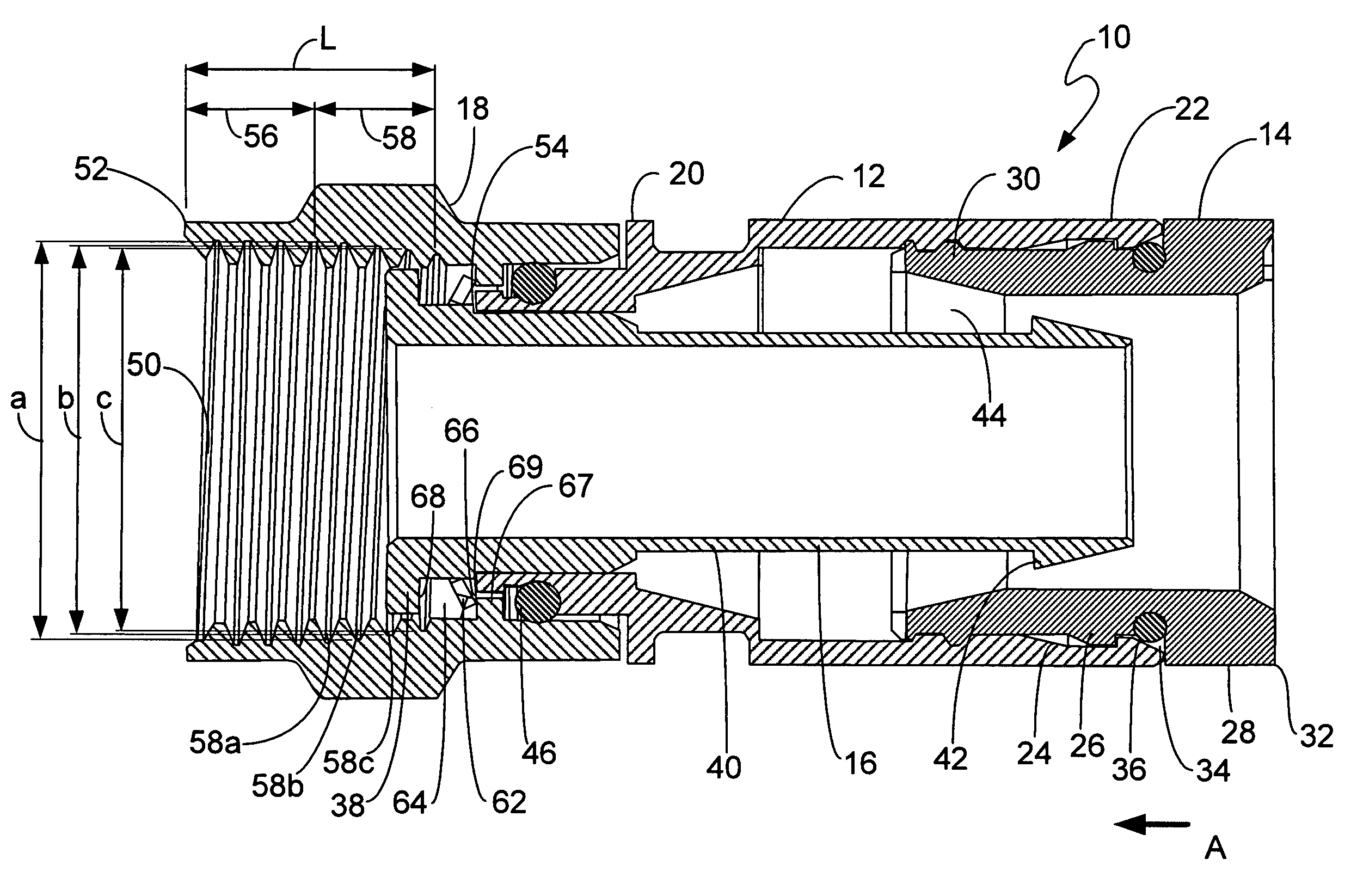
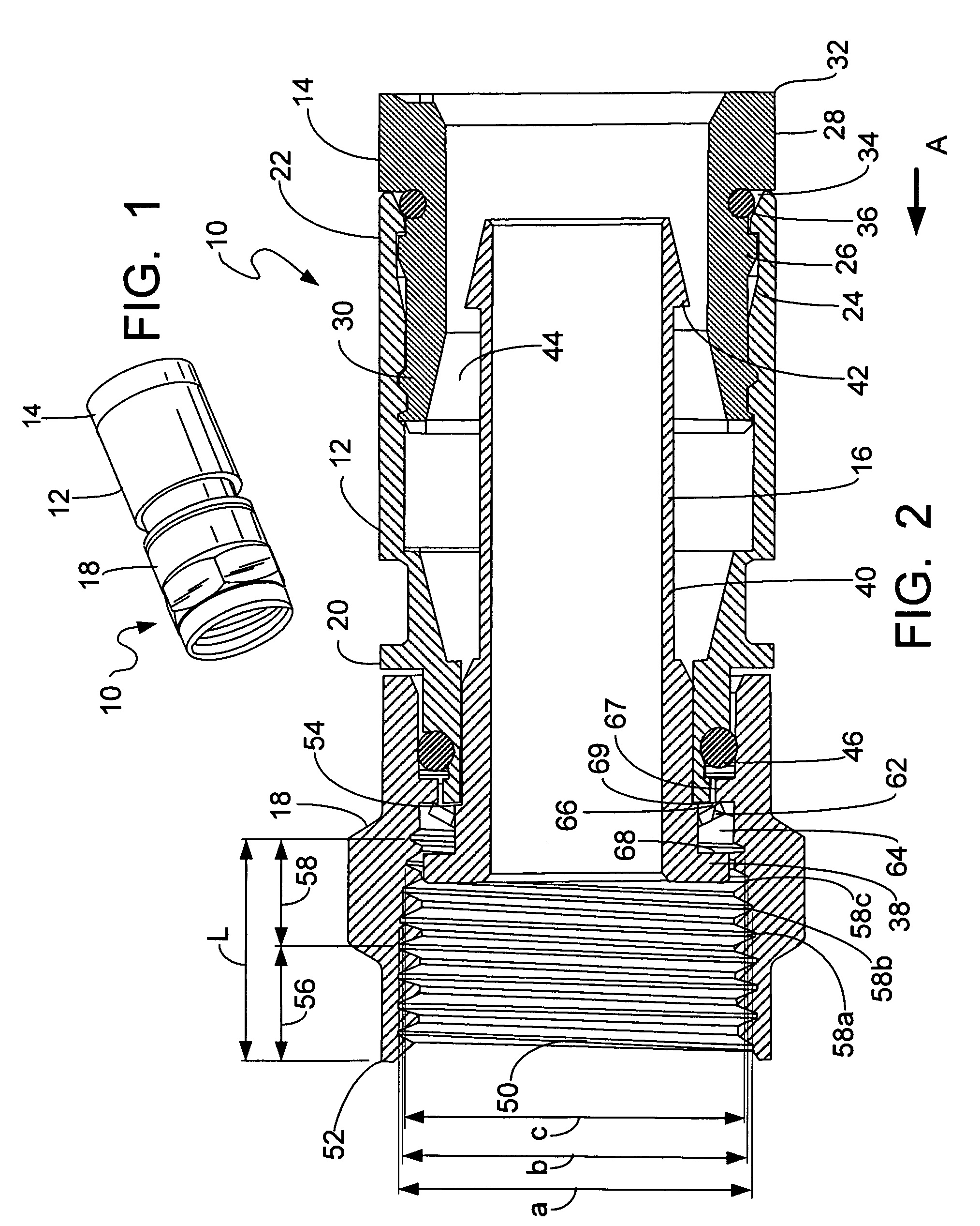
[0026]Referring first to FIGS. 1 and 2, a preferred embodiment of the coaxial cable connector 10 of the present invention is shown. The connector 10 generally includes a connector body 12, a locking sleeve 14, an annular post 16 and a rotatable nut 18.

[0027]The connector body 12, also called a collar, is an elongate generally cylindrical member, which can be made from plastic or from metal or the like. The body 12 has a forward end 20 coupled to the post 16 and the nut 18 and an opposite cable receiving end 22 for insertably receiving the locking sleeve 14, as well as a prepared end of a coaxial cable in the forward direction as shown by arrow A. The cable receiving end 22 of the connector body 12 defines an inner sleeve engagement surface for coupling with the locking sleeve 14. The inner engagement surface is preferably formed with a groove or recess 24, which cooperates with mating detent structure 26 provided on the outer surface of the locking sleeve 14.

[0028]The locking sleeve...


PUM


Abstract

A coaxial cable connector generally includes a connector body, a nut rotatably coupled to the connector body, a post disposed in the connector body and a biasing element acting between the post and the nut. The nut has an internal thread for engagement with an external thread of a mating connector. The internal thread of the nut and the external thread of the mating connector can be mismatched, wherein an interference fit is created therebetween upon connection of the nut to the mating connector. Also, the post can have a forward flanged base portion disposed within the axial length of the internally threaded surface of the nut, which, together with the biasing element, provides a constant force between the post and the nut.

Description

CROSS-REFERENCE TO RELATED APPLICATIONS[0001]This application claims the benefit of U.S. Provisional Application No. 60 / 943,943, filed on Jun. 14, 2007, which is incorporated by reference herein in its entirety for all purposes.BACKGROUND OF THE INVENTION[0002]The present invention relates generally to connectors for terminating coaxial cable. More particularly, the present invention relates to a coaxial cable connector having structural features to positively secure the connector to any F port regardless of the type of material, casting or plating specifications.[0003]It has long been known to use connectors to terminate coaxial cable so as to connect a cable to various electronic devices such as televisions, radios and the like. Prior art coaxial connectors generally include a connector body having an annular collar for accommodating a coaxial cable, an annular nut rotatably coupled to the collar for providing mechanical attachment of the connector to an external device and an ann...

Claims


Application Information

Patent Timeline
IPC IPC(8): H01R9/05
CPCH01R9/0524H01R13/5202H01R13/622H01R24/40H01R2103/00H01R24/38H01R13/52
Inventor MALLOY, ALLENRADZIK, JACKDEAN, MIKEHAUVER, BRUCEKNAUS, GARYTHOMAS, CHARLES
Owner PPC BROADBAND INC
Why Eureka
Try Eureka