Compost Ventilation

a technology of compost heap and ventilation pipe, which is applied in the field of ventilation pipe, can solve the problems of affecting the ventilation of compost heap, and prone to damage, and achieves the effect of facilitating the connection of ventilation pip

Inactive Publication Date: 2008-12-18
COVERED SYST
View PDF4 Cites 1 Cited by
  • Summary
  • Abstract
  • Description
  • Claims
  • Application Information

AI Technical Summary

Benefits of technology

[0018]It is preferred that there are a plurality of ventilation pipes having ventilation portions within the compost heap so that the aeration is distributed throughout the compost heap as this helps to avoid ‘hot spots’ or areas of high or low aeration.
[0019]The ventilation pipe is preferably arranged substantially vertically within the compost heap such that the connection end extends above an upper surface of the heap. This facilitates connection of the ventilation pipe to the air moving means and can help to prevent the ventilation pipe from filling with compost material which may occur if material can fall through the aeration holes.

Problems solved by technology

However, such vent channels can be costly to build into the, typically concrete, floor.
However the channels are constructed on the floor they are vulnerable to damage by machinery used to transport the compost material as the compost heap is built over the channels.

Method used


Image

  • Compost Ventilation
  • Compost Ventilation
  • Compost Ventilation

Examples


Embodiment Construction

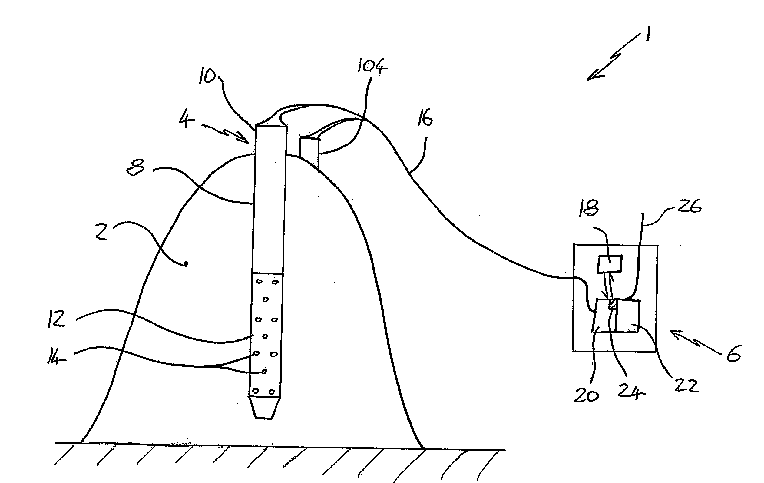
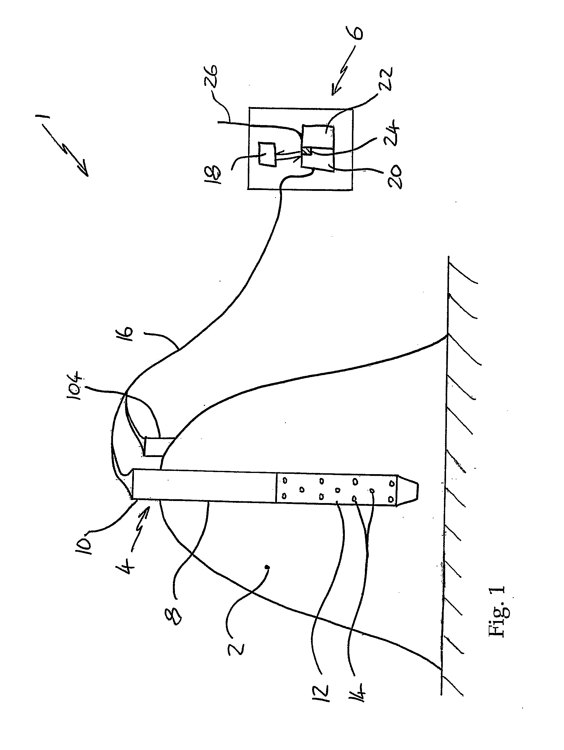
[0024]FIG. 1 shows a composting apparatus 1 comprising a compost heap 2 comprising compostable material. There is at least one ventilation pipe 4 and air moving means 6, in this case a fan. The ventilation pipe 4 comprised a pipe wall 8 defining a conduit 10 for gas. The ventilation pipe 4 has a connection end 10 and a ventilation portion 12. The ventilation portion 12 has a plurality of aeration holes 14 extending through the pipe wall 8. The ventilation portion 12 is located within the compost heap 2 and the connection end 10 is coupled to the air moving means 6 by a pipe 16 such that, when active, the air moving means 6 causes movement of air through the aeration holes 14 towards the air moving means 6. In this case the ventilation pipe is a 76 mm outer diameter steel pipe having a wall thickness of 3 mm.

[0025]The air moving means 6 comprise a controller 18, an air mover 20, a filter 22 and a sensor 24. The controller 18 receives a signal from the sensor 24 and controls the air m...


PUM


Abstract

The invention relates to a method of ventilating a compost heap. The method comprises using at least one ventilation pipe and an air moving means, the ventilation pipe comprising a pipe wall defining a conduit for gas and the ventilation pipe having a connection end and a ventilation portion, the ventilation portion having a plurality of aeration holes extending through the pipe wall and the method comprising the steps of: constructing a compost heap comprising compostable materials; inserting the ventilation portion of the at least one ventilation pipe into the compost heap; connecting the connection end of the ventilation pipe to the air moving means; using the air moving means to cause movement of air through the aeration holes; in which the step of inserting the ventilation portion into the compost heap comprises the steps of: coupling the ventilation pipe to a piler apparatus; using the piler apparatus to drive the ventilation pipe into the compost heap; releasing the piler apparatus from the ventilation pipe; and retrieving the piler apparatus from the ventilation pipe.

Description

BACKGROUND[0001]a. Field of the Invention[0002]The present invention relates to a method of ventilating a compost heap, in particular to the ventilation of compost heaps and windrows so as to reduce odour.[0003]b. Related Art[0004]Composting of compostable material is typically performed in heaps. These heaps may be located inside buildings or outside. If the compost heap is located outside, it is typically in the form of an elongate row called a windrow. Compost heaps may be agitated or turned during the composting process to aerate the content to ensure efficient composting. Compostable material is used herein to include biodegradable materials such as household waste and other waste materials.[0005]It is known to have vent channels located on the floor of a building in which a compost heap is to be located. The vent channels in the floor either blow air into the base of the compost heap, or draw air from the base of the heap. This air movement through the base of the heap ventila...

Claims


Application Information

Patent Timeline
Patent Type & Authority Applications(United States)
IPC IPC(8): F24F7/00
CPCC05F17/0264C05F17/027C05F17/0282C05F17/971C05F17/979C05F17/993Y02P20/145Y02W30/40C05F9/02C05F17/90
Inventor JARDINE, JOHNWATCHORN, SIMON JAMES
Owner COVERED SYST
Why Eureka
Try Eureka