Injection Device

a technology of injection device and injection needle, which is applied in the direction of injection needle, intravenous device, automatic syringe, etc., can solve the problems of inability to reproduce, difficult to perform these steps, and unlikely to be able to do so for a long time to com

Active Publication Date: 2008-12-18
CILAG GMBH INT
View PDF99 Cites 31 Cited by
  • Summary
  • Abstract
  • Description
  • Claims
  • Application Information

AI Technical Summary

Benefits of technology

[0004]It is an object of the present invention to provide a construction of injection device in which possible misalignment between the drive ...

Problems solved by technology

However, there is one faculty of a production line worker that, hitherto, machines have been unable to reproduce, and are unlikely to be able to do so for a long time to come.
If a part is damaged, he may discard it.
Difficulties in performing these steps may arise from tight component tolerances or from the use of fragile components, such as glass hypodermic syringes.
Secondly, this flat end fac...

Method used


Image

  • Injection Device
  • Injection Device
  • Injection Device

Examples


Embodiment Construction

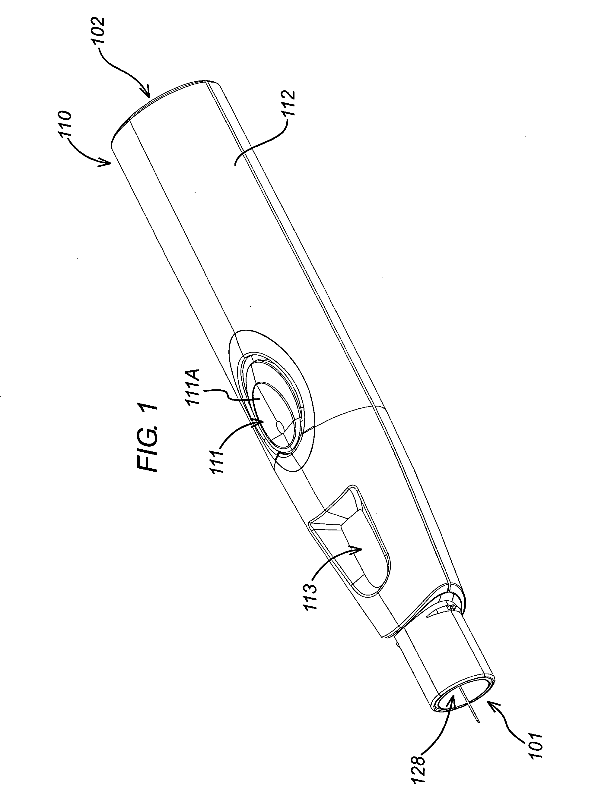
[0028]FIG. 1 shows an injection device 110 having a housing 112 with a proximal end 101 and a distal end 102. All parts are injection-moulded. The housing 112 has a trigger 111 which projects through the housing 112 and which can be actuated by pressing down on its upper surface 111a. There is a indicator opening 113 in the housing located adjacent the proximal end 101.

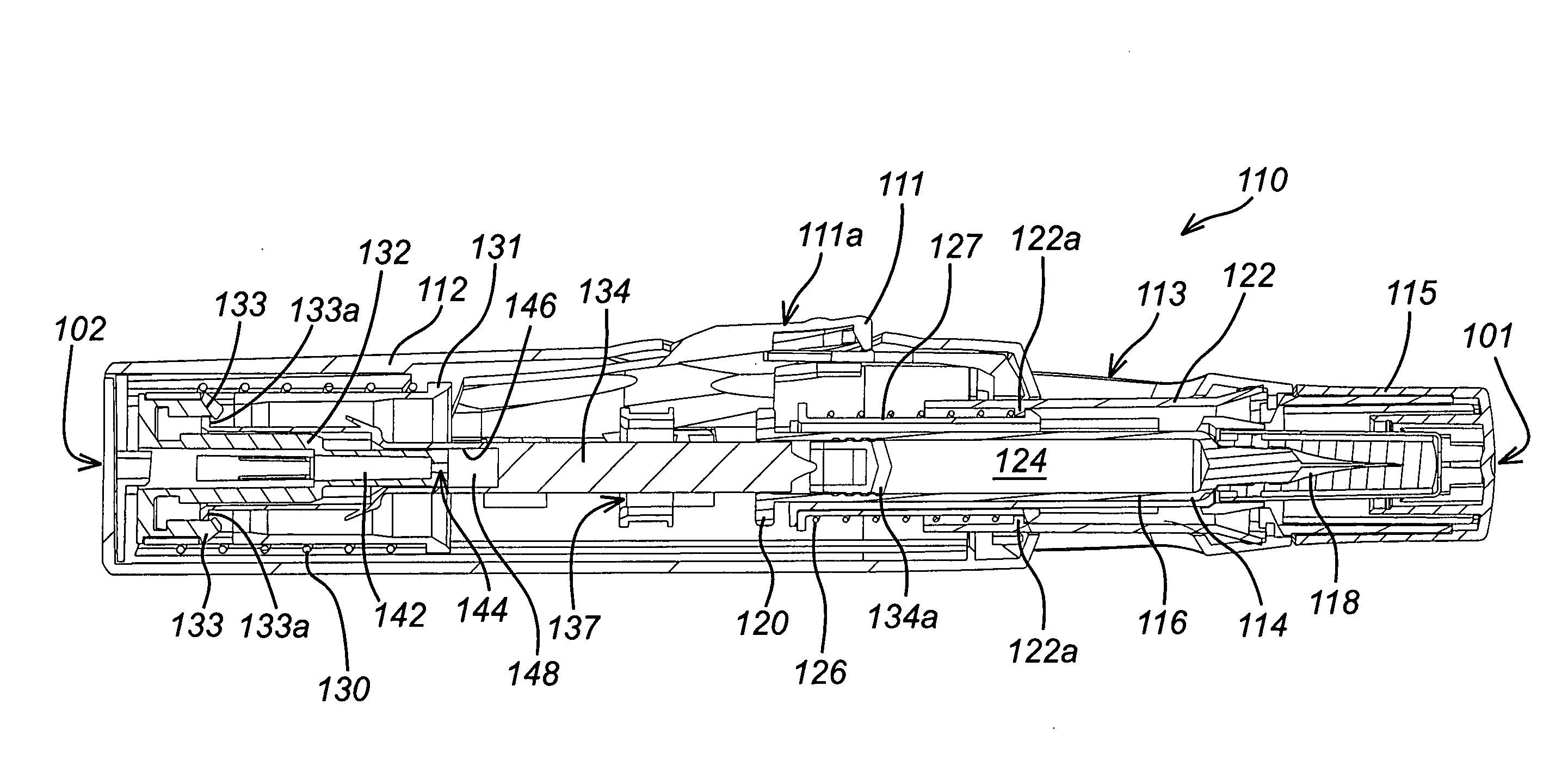
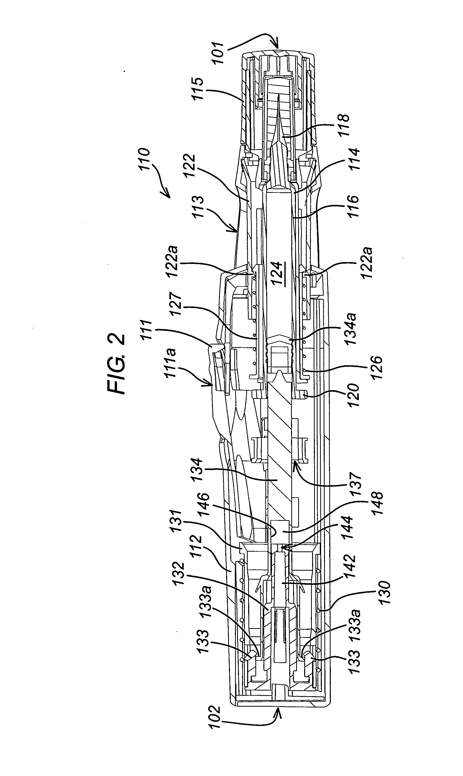
[0029]FIG. 2 shows the housing 112 containing a hypodermic syringe 114 of conventional type, including a syringe body 116 terminating at one end in a hypodermic needle 118 and at the other in a flange 120. The conventional plunger and bung that would normally be used to discharge the contents of the syringe 114 manually have been removed and replaced with a drive element 134 which includes a bung 134a. This drive element 134 constrains a drug 124 to be administered within the syringe body 116. Whilst the syringe illustrated is of hypodermic type, this need not necessarily be so. Transcutaneous or ballistic dermal and ...


PUM


Abstract

An injection device is described. A syringe 114 is received within a housing, the syringe having a bore terminating at a forward end in a hypodermic needle 118 and at a rearward end in a flared opening 210 in which a bung 134a having a bore 206 surrounded by a skirt 208 is inserted. A drive element 134 has a forward end consisting of a substantially flat annular region 200 that bears upon the skirt 208 of the bung 134a and surrounds a conical middle region 202 that is received in the bore 206 of the bung 134a. An actuator advances the drive element 134 so as to advance the bung 134a and discharge the contents of the syringe through the needle 118. The opening 210 in the rear of the glass syringe is flared by being provided with a radius. The combination of the radius at the opening 210 and the projecting conical middle region 202 of the drive element allows misalignments of the two to be managed during automated assembly. This is because the conical middle region 202 either pass straight into the opening 210 of the syringe, or contact the radius, which guides them towards the centre of the syringe bore. The radius and the substantially flat annular region 200 and the central conical portion 202 of the drive element 134 are so shaped and dimensioned that axial misalignment between the syringe 114 and the drive element 134 during assembly of the injection device are corrected by, firstly, the conical middle region 202 of the drive element 134 riding up the radius to a point at which, secondly, the substantially flat annular region 200 also makes contact with and rides up the radius, to align the drive element 134 in the bore of the syringe 114.

Description

BACKGROUND TECHNOLOGY[0001]The present invention is concerned with injection devices of the type that include a housing, a syringe received within the housing, the syringe having a bore in which a discharge piston having a bore is inserted, a drive element and an actuator for advancing the drive element so as to advance the discharge piston and discharge the contents of the syringe through its discharge nozzle.[0002]These days, nearly everything is manufactured by machines. In some circumstances, machines are more reliable that manual labour and are they are very much less expensive. However, there is one faculty of a production line worker that, hitherto, machines have been unable to reproduce, and are unlikely to be able to do so for a long time to come. If a production line worker drops a part of the thing being manufactured, he may pick it up or he may select another from the parts bin. If a part is damaged, he may discard it. If the assembly operation he is undertaking is compl...

Claims


Application Information

Patent Timeline
IPC IPC(8): A61M5/315A61M5/20A61M5/32
CPCA61M5/2033A61M5/31511A61M5/3202A61M5/3204A61M5/326A61M5/31513
Inventor HARRISON, NIGELHABESHAW, ROSEMARY
Owner CILAG GMBH INT
Why Eureka
Try Eureka