

Vehicle driving position control system and method
a technology for controlling system and driving position, applied in the direction of movable seats, process and machine control, instruments, etc., can solve the problems of system not being able to cope with the change in the preference of each user, and the inability to adjust the driving position
- Summary
- Abstract
- Description
- Claims
- Application Information
AI Technical Summary
Benefits of technology
Problems solved by technology
Method used
Image

Examples
first embodiment
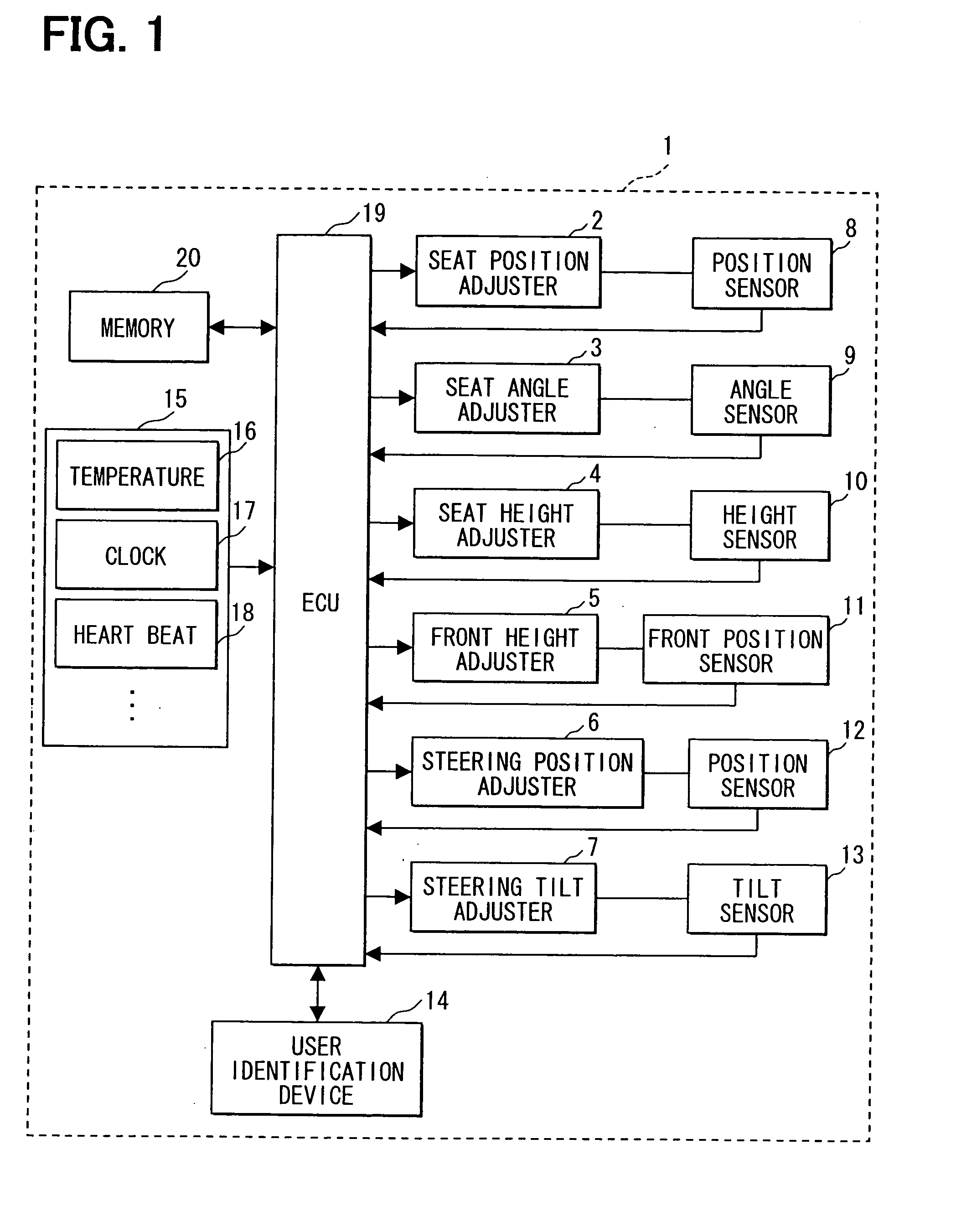
[0015]Referring first to FIG. 1, a driving position control system 1 for a vehicle has various devices for adjusting the driving position of a driver, who is a user of the control system 1. The adjusting devices are a seat position adjuster 2, a seat angle adjuster 3, a seat height adjuster 4, a seat front height adjuster 5, a steering wheel position adjuster 6, and a steering wheel tilt adjuster 7. The adjusters 1 to 5 adjust the driver seat (not shown) of the control system 1. The adjusters 6 and 7 adjust the steering wheel (not shown) of the control system 1.
[0016]In accordance with a user's switching operation or the like, the seat position adjuster 2 adjusts the position of the driver seat forward and backward by means of an electric motor or another driving source. In accordance with a user's switching operation or the like, the seat angle adjuster 3 adjusts the angle of the back of the driver seat similarly to the seat position adjuster 2. In accordance with a user's switchin...
second embodiment
[0049]According to a second embodiment, the control system 1 has a radio communication device 24 in place of the user identification device 14. Otherwise, the control system 1 is substantially identical in structure with the control system 1 shown in FIG. 1. The communication device 24 communicates with a portable device 30, which may be a cell phone or an IC card. Each portable device 30 is carried by a user and stores his or her user identifier. The ECU 19 of this system identifies the user by acquiring his or her user identifier from his or her portable device 30 through the communication device 24.
[0050]Each portable device 30 might be fitted with a memory which stores statistical data and likelihood data so that the ECU 19 could acquire statistical data and likelihood data by means of radio communication between the communication device 24 and portable device 30. In this case, if a user gets into a rental car or another vehicle which is of the same type as the vehicle, it is po...
third embodiment
[0051]According to a third embodiment, the control system 1 is identical with the control system shown in FIG. 5. The communication device 24 communicates with a data management station 40, which has a memory (database) 43 for storing statistical data and likelihood data. The management station 40 is capable of a plurality of control systems of other vehicles which are identical with that shown in FIG. 6.
[0052]The data management station 40 has a communication device 41 and an ECU 42. The communication device 41 communicates with the vehicle communication device 24 of each control system 1. The management station 40 stores the statistical data and likelihood data for two or more users. The ECU 42 identifies the users and distinguishes the data for them. This makes it necessary to use user ID information additionally for the communication between each control system 1 and the management station 40. Each vehicle communication device 24 may store user ID information and transmit it to ...
PUM
 Abstract
Description
Claims
Application Information