Electronic Parallel Lift And Return To Carry On A Backhoe Loader

a backhoe loader and electric parallel technology, applied in the direction of electric programme control, program control, instruments, etc., can solve the problems of increasing operator fatigue and reducing overall work efficiency

Active Publication Date: 2008-12-25
DEERE & CO
View PDF9 Cites 31 Cited by
  • Summary
  • Abstract
  • Description
  • Claims
  • Application Information

AI Technical Summary

Benefits of technology

The invention allows for more control over a loaders' tools including returning to carrying position, retracting back into the machine, and preventing the buckets from spilling their loads while driving.

Problems solved by technology

This patent describes how different types of work vehicles like loaders and excavators can be outfitted with tools to perform specific tasks. However, controlling the orientation of these tools while moving them around can require a lot of focus from the operator and result in decreased productivity. To solve this problem, several companies have developed automatic control systems for the tools using sensors and feedback loops. These systems help keep the tools oriented correctly without requiring excessive operator attention.

Method used


Image

  • Electronic Parallel Lift And Return To Carry On A Backhoe Loader
  • Electronic Parallel Lift And Return To Carry On A Backhoe Loader
  • Electronic Parallel Lift And Return To Carry On A Backhoe Loader

Examples


Embodiment Construction

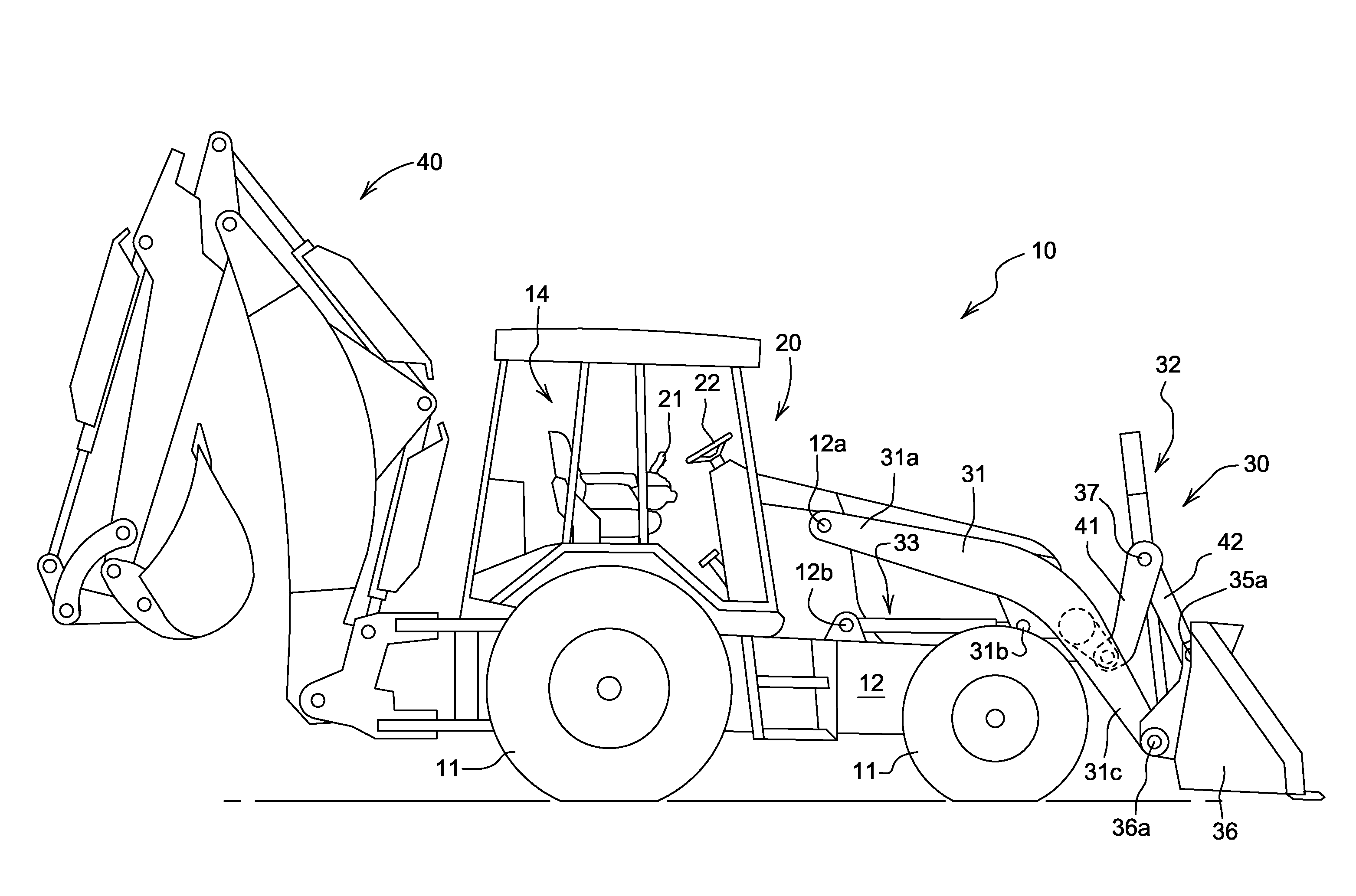
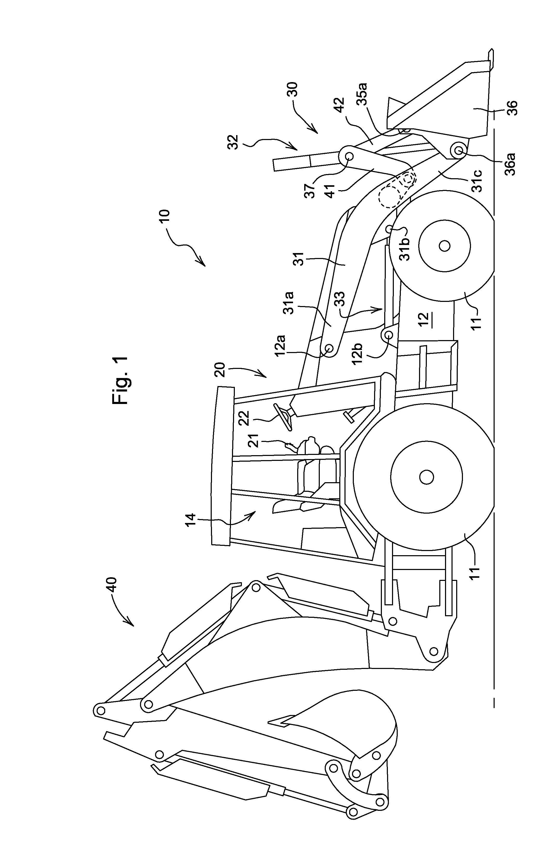
[0028]FIG. 1 illustrates an exemplary work vehicle, i.e., a backhoe loader 10 in which the invention may be utilized. The backhoe loader 10 has a frame 12, to which are attached ground engaging wheels 11 for supporting and propelling the vehicle 10. Attached to the front of the vehicle is a loader assembly 30, and attached to the rear of the vehicle 10 is a backhoe assembly 40. Both the loader assembly 30 and backhoe assembly 40 perform a variety of material handling functions. An operator controls the functions of the vehicle 10 from an operator's station 20.

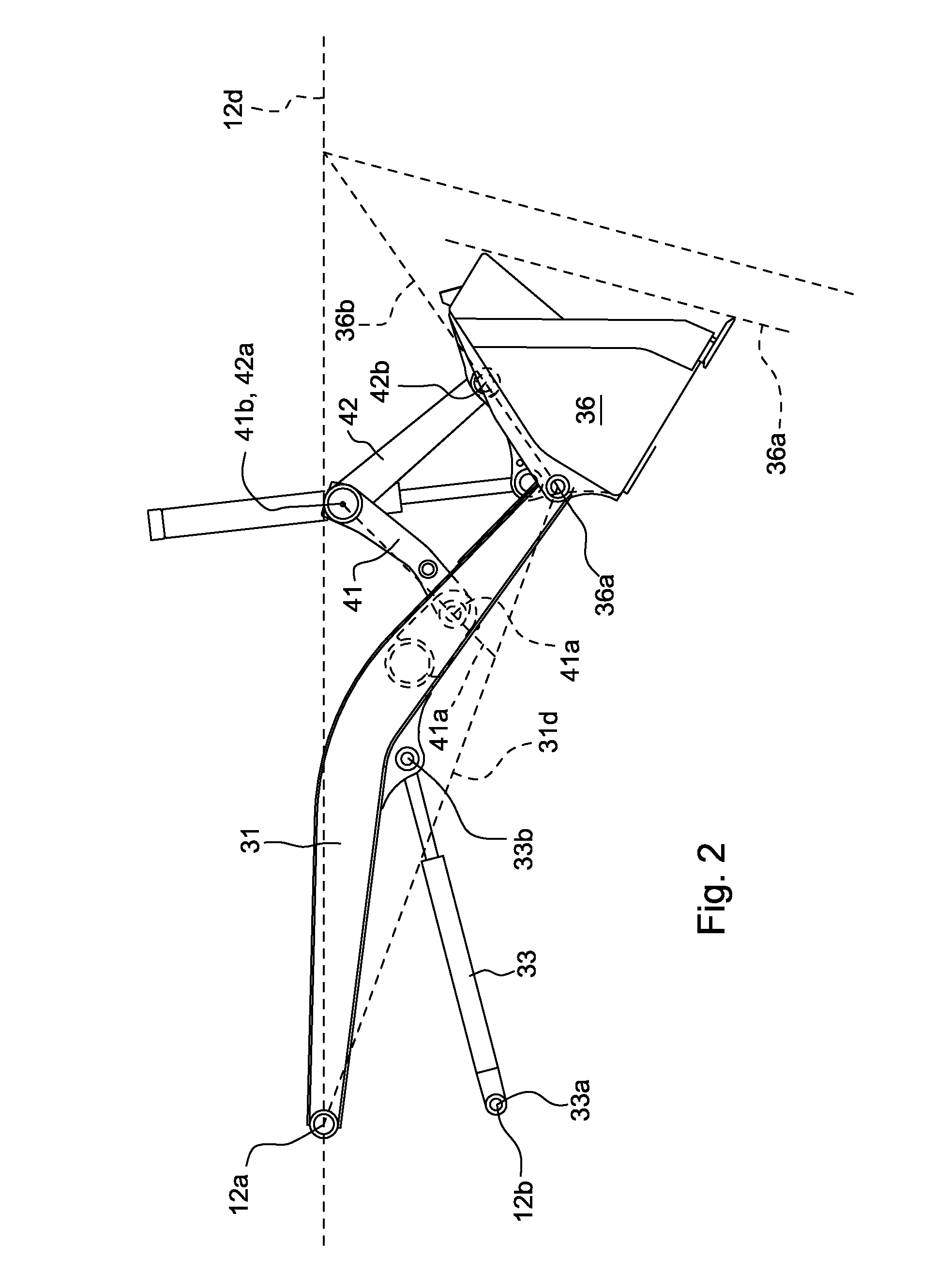
[0029]This particular loader assembly 30 comprises a loader boom 31, a linkage 40 and a tool such as, for example, a loader bucket 36. The loader boom 31 has a first end 31a pivotally attached to the frame 12 at a horizontal loader boom pivot 12a, and a second end 31c to which the loader bucket 36 pivotally attaches at loader bucket pivot 36a.

[0030]The linkage 40, illustrated in FIG. 2, includes a boom link 41 and a bucket lin...


PUM


Abstract

A backhoe loader with a controller that uses angular signals from at least one sensor to calculate a loader tool angle with respect to the vehicle frame or with respect to the earth and to maintain the loader tool angle via controller generated commands to a tool actuator as a function of the angular signals and commands to a boom actuator. The controller enables proportional control of the tool angle via a command input device such as an electronic joystick. If the electronic joystick is moved to an appropriate detent position, the controller executes a return to carry function.

Description


Claims


Application Information

Patent Timeline
Owner DEERE & CO
Why Eureka
Try Eureka