Well Treatment Device, Method and System

Active Publication Date: 2008-12-25
PIONEER NATURAL RESOURCES USA
View PDF28 Cites 26 Cited by
  • Summary
  • Abstract
  • Description
  • Claims
  • Application Information

AI Technical Summary

Benefits of technology

[0004]It is an object of at least some examples of the present invention to provide for well-treatment devices, systems,

Problems solved by technology

The packers become stuck in the well-bore, however, result

Method used


Image

  • Well Treatment Device, Method and System
  • Well Treatment Device, Method and System
  • Well Treatment Device, Method and System

Examples


Embodiment Construction

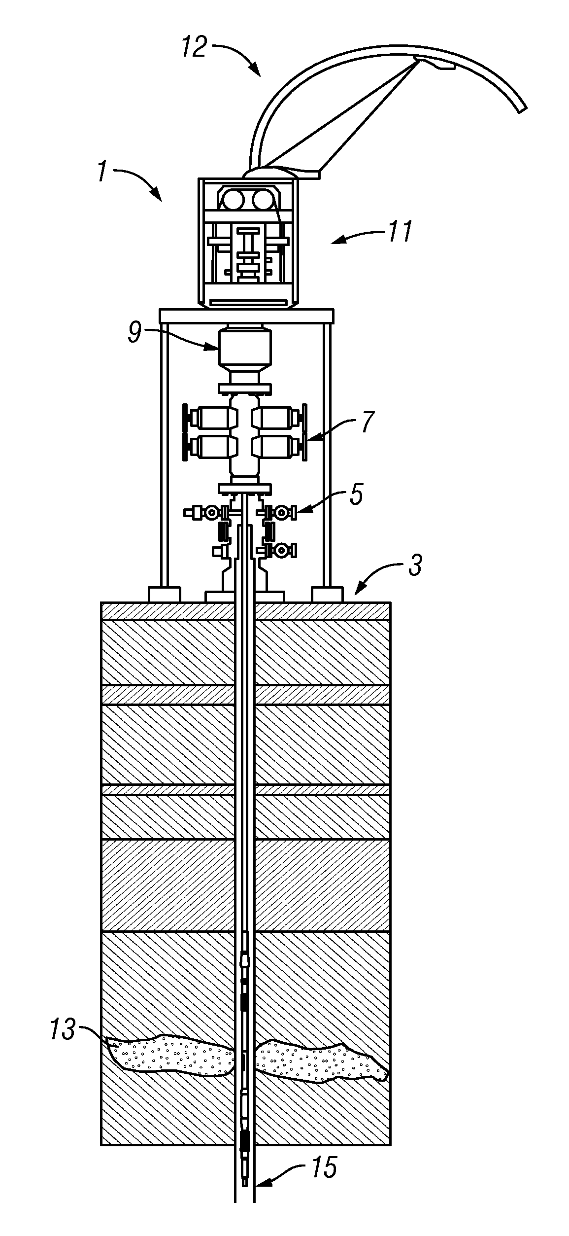
[0090]Referring now to FIG. 1, a well-site, generally designated by the numeral 1, is seen. In the figure, a well-head 5 that is attached to the ground 3 has blow-out preventers 7 attached to the well head 5. A lubricator 9 is seen connected under injector 11 that injects coiled tubing 12, through lubricator 9, blow-out preventer 7, well-head 5, and into the well-bore. In many situations, the well-bore is cased with casing 15. Seen in the well-bore at an oil and / or gas, strata 13 is an example of the present invention straddling the oil and / or gas strata 13.

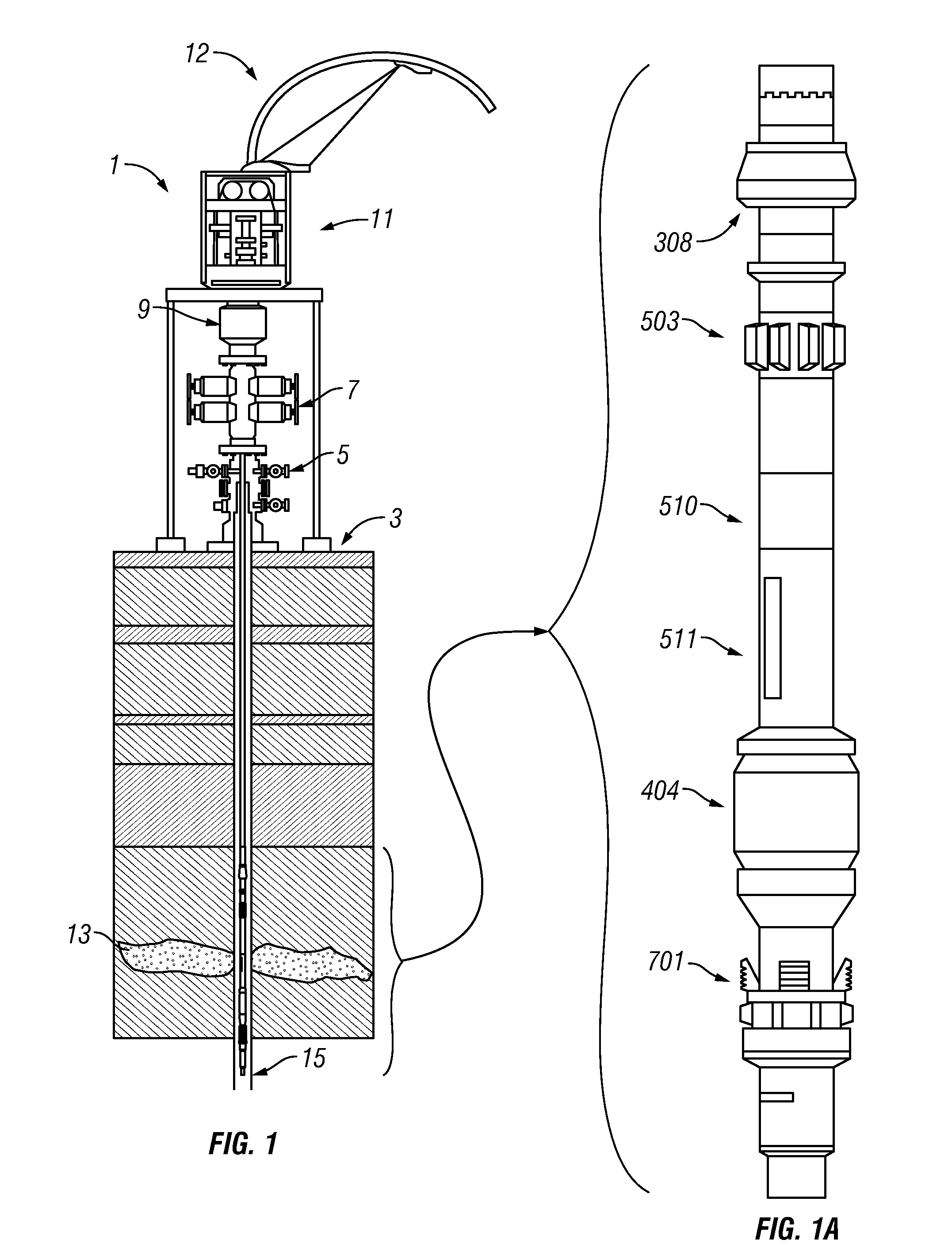
[0091]In FIG. 1A, an enlargement of the example from FIG. 1 is seen in which a cup packer 308 is connected through centralizer section 503, spacer joint 510, ported section 511, expansion packer section 404, and well-bore engagement section 701. FIG. 2 and FIGS. 2A-2F show enlargements of each of the sections discussed above.

[0092]Referring now to FIG. 3, a cross-section of an example cup-packer assembly is seen comprising a top ...


PUM


Abstract

System, devices, and methods are described relating to the treatment (e.g., perforating, fracturing, foam stimulation, acid treatment, cement treatment, etc.) of well-bores (e.g., cased oil and/or gas wells). In at least one example, a method is provided for treatment of a region in a well, the method comprising: positioning, in a well-bore, a packer above the region of the well-bore, fixing, below the region, an expansion packer, treating the region, the treatment fixing the packer, moving the expansion packer, and moving the packer after the moving of the expansion packer.

Description

BACKGROUND[0001]The invention relates to tools and methods of treatment of well-bores that are used, for example, in the exploration and production of oil and gas.[0002]In many of the well-bores (as illustrated, for example, in U.S. Pat. No. 6,474,419, incorporated herein by reference) so-called “packers” are run in on a work string (for example, coiled tubing), to allow for treatment of the well-bore by perforation of casing and / or fracturing operations. The packers become stuck in the well-bore, however, resulting in lost tools and, sometimes, loss of the entire well.[0003]There is a need, therefore, for improved well treatment devices, systems, and methods.SUMMARY OF THE INVENTION[0004]It is an object of at least some examples of the present invention to provide for well-treatment devices, systems, and methods, that reduce the chance of having a tool stuck in a well and / or for more efficient well-treatment procedures.[0005]In at least one example of the invention, a method is pro...

Claims


Application Information

Patent Timeline
IPC IPC(8): E21B33/12E21B23/00E21B43/00
CPCE21B23/006E21B23/06E21B43/25E21B33/126E21B33/1294E21B33/124
Inventor HOWARD, DUSTINMANDRELL, PHILLIPSTROMQUIST, MARTY
Owner PIONEER NATURAL RESOURCES USA
Why Eureka
Try Eureka