Charger for battery packs and combination of battery packs and a charger

Active Publication Date: 2008-12-25
MAKITA CORP
View PDF4 Cites 11 Cited by
  • Summary
  • Abstract
  • Description
  • Claims
  • Application Information

AI Technical Summary

Benefits of technology

[0013]The battery pack socket preferably has a partial area for commonly accepting a part of the first-type battery pack and a part of the second-type battery pack. In accepting the first-type battery pack into the battery pack socket and in accepting the second-type battery pack likewise, parts of the first-type battery pack and the second-type battery pack fit into the partial area. That is, the partial area overlappingly accepts the first-type battery pack and the second-type battery pack. As a result, the size of the battery pack socket can be reduced and thereby the size of the charger can be reduced.
[0014]In a case where each of the first-type battery pack and the second-type battery pack has at least a pair of electrode terminals, and a positional relationship of the pair of electrode terminals of the first-type battery pack is identic

Problems solved by technology

Likewise, the battery pack socket preferably has a shape that does not allow insertion of t

Method used


Image

  • Charger for battery packs and combination of battery packs and a charger
  • Charger for battery packs and combination of battery packs and a charger
  • Charger for battery packs and combination of battery packs and a charger

Examples


Example

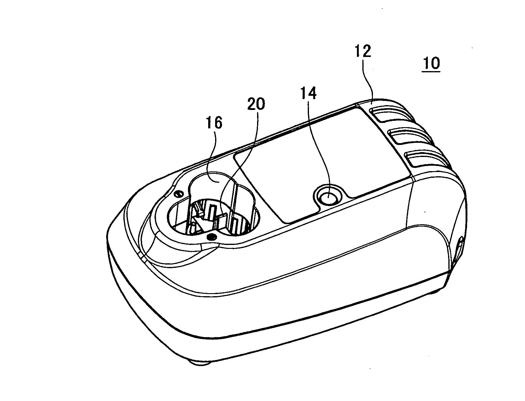
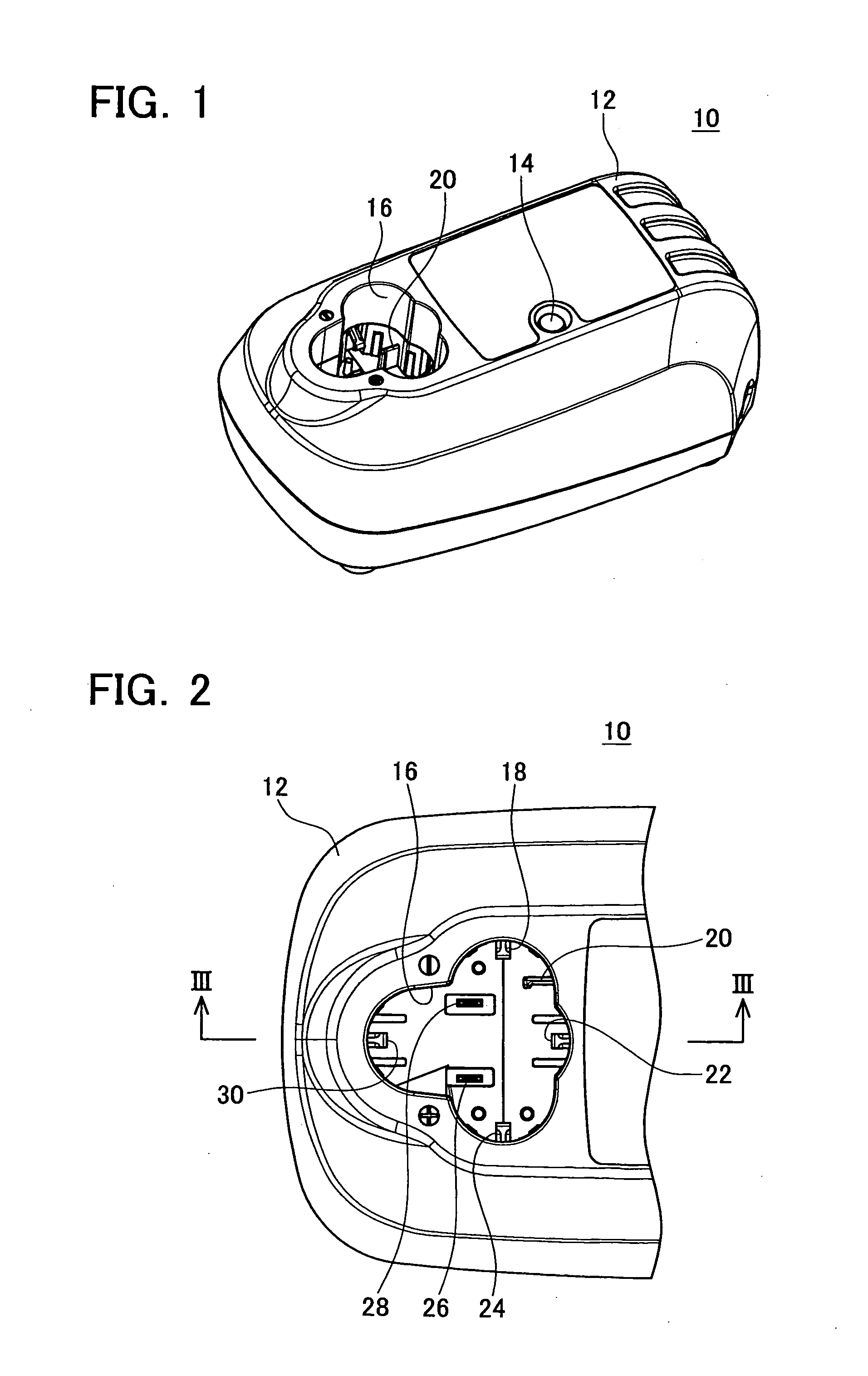
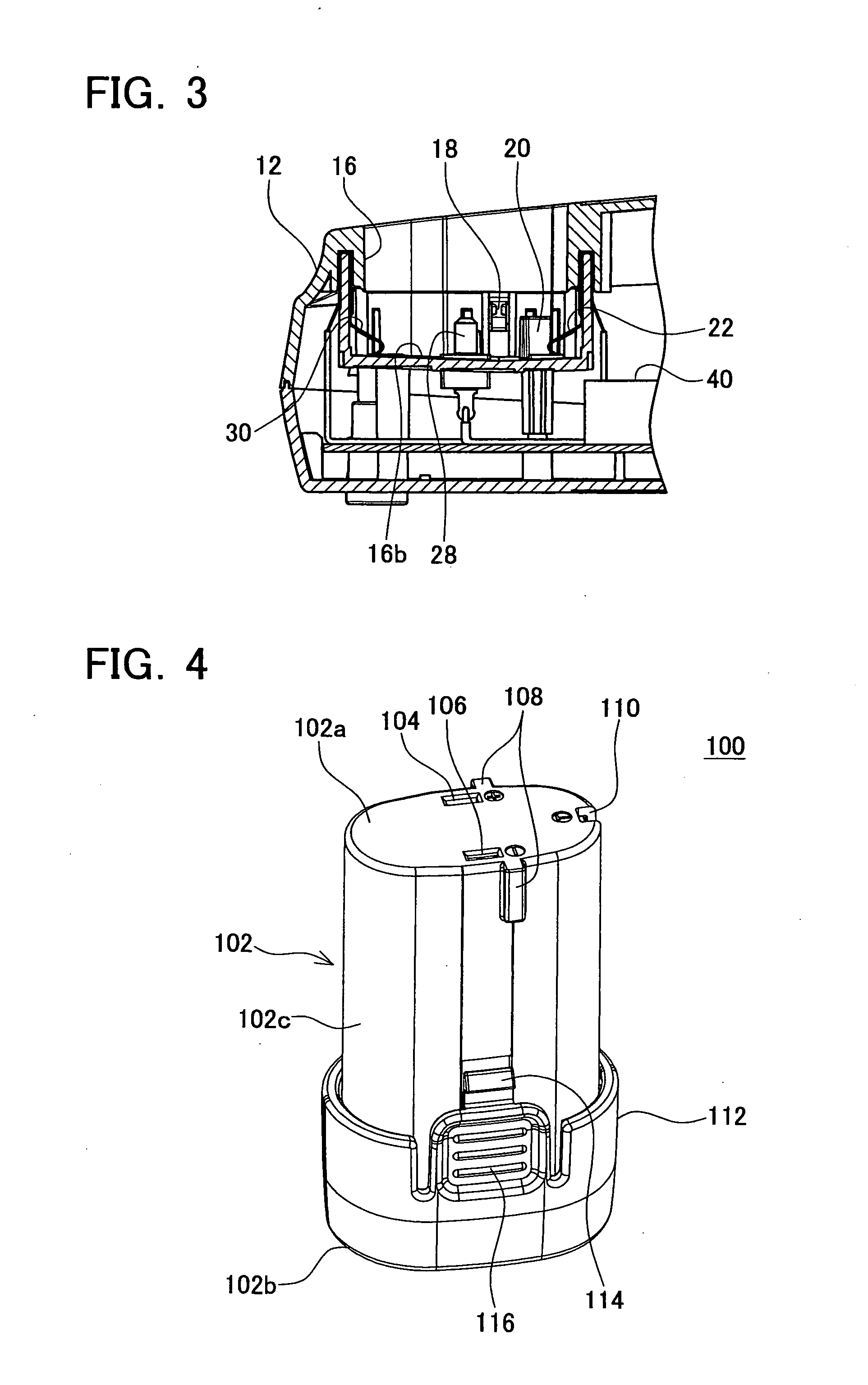
[0029]Below are some of the characteristic features of an embodiment of the invention[0030](Feature 1) The case of the first-type battery pack houses two battery cells. The case of the first-type battery pack is formed in a pillar shape having an approximately elliptic cross-sectional shape. The one end portion of the case of the first-type battery pack is the insertion portion for inserting the battery pack socket.[0031](Feature 2) The case of the second-type battery pack houses three battery cells. The case of the second-type battery pack is formed in a pillar shape having a cross-sectional shape where one ellipse is connected to an approximately half ellipse in a T-shape. The one end portion of the case of the second-type battery pack is the insertion portion for inserting the battery pack socket.[0032](Feature 3) The pair of electrode terminals of the first-type battery pack and a pair of electrode terminals of the second-type battery pack have substantially the same structures ...


PUM


Abstract

A charger is adopted to charge a first-type battery pack and a second-type battery pack, each type of battery packs having an insertion portion whose shapes are different. The charger is provided with a housing having a battery pack socket for inserting the battery packs. The battery pack socket has a shape that allows the insertion portion of the first-type battery pack and the insertion portion of the second-type battery pack to be inserted thereto selectively in a prescribed attitude. A pair of output terminals that output charging power is disposed within the battery pack socket. The pair of output terminals is electrically connected to the first-type battery pack when the insertion portion of the first-type battery pack is inserted into the battery pack socket in the prescribed attitude. Likewise, the pair of output terminals is electrically connected to the second-type battery pack when the insertion portion of the second-type battery pack is inserted into the battery pack socket in the prescribed attitude.

Description

CROSS-REFERENCE TO RELATED APPLICATION[0001]This application claims priority to Japanese Patent Application No. 2007-165080, filed on Jun. 22, 2007, the contents of which are hereby incorporated by reference into the present application.BACKGROUND OF THE INVENTION[0002]1. Field of the Invention[0003]The present invention relates to a technique of charging a battery pack. Particularly, the invention relates to a technique of charging various types of battery packs with a single charger.[0004]2. Description of the Related Art[0005]Many electric appliances such as a portable electric power tool powered by a detachable battery pack are used. Rechargeable battery cells, which can be charged repeatedly by a charger, are installed in the battery pack used in this type of electric appliances.[0006]Battery packs are designed in various shapes in accordance with electric appliances in which they are used, and therefore an exclusive charger is provided respectively for each type of battery pac...

Claims


Application Information

Patent Timeline
IPC IPC(8): H02J7/02H02J7/00
CPCH02J7/0003H02J7/0013H02J7/0045H02J7/00047
Inventor KONDO, EIJI
Owner MAKITA CORP
Why Eureka
Try Eureka