Display apparatus and driving method thereof

a technology of display apparatus and driving method, which is applied in the direction of cathode-ray tube indicators, identification means, instruments, etc., can solve the problems of reducing the life of the display apparatus and reducing the contrast, increasing the cost, and limiting the brightness and contrast. , to achieve the effect of lowering the contrast and increasing the cos

Inactive Publication Date: 2008-12-25
CANON KK
View PDF6 Cites 6 Cited by
  • Summary
  • Abstract
  • Description
  • Claims
  • Application Information

AI Technical Summary

Benefits of technology

[0010]An object of the present invention is to provide a display apparatus capable of switching a display state between a plurality of display states without increasing the number of electrodes.
[0050]In the present invention, display is effected by changing a dispersion state of migration particles through application of a DC voltage to electrode(s) and by moving the migration particles to a strong electric field area or a weak electric field area of a non-uniform electric field generated by a non-uniform electric field generation structure through application of an AC voltage to electrode(s). As a result, it becomes possible to effect switching between a plurality of display states without increasing the number of electrodes. Further, it is possible to obviate an increase in cost due to complicate process and a load on a driver. Further, it is also possible to obviate such a problem that an increase in area of electrode in each pixel impairs an aperture ratio, thus lowering a contrast.

Problems solved by technology

In such an electrophoretic display apparatus, however, there has arisen a problem such that a life of the display apparatus and a contrast are lowered due to inclusion of the coloring agent such as a dye.
When the number of electrodes is increased, a process is complicated and a load is placed on a driver, thus leading to an increase in cost.
As a result, a brightness and a contrast are limited.

Method used


Image

  • Display apparatus and driving method thereof
  • Display apparatus and driving method thereof
  • Display apparatus and driving method thereof

Examples


first embodiment

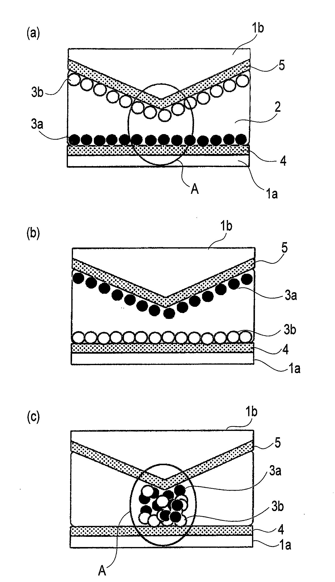
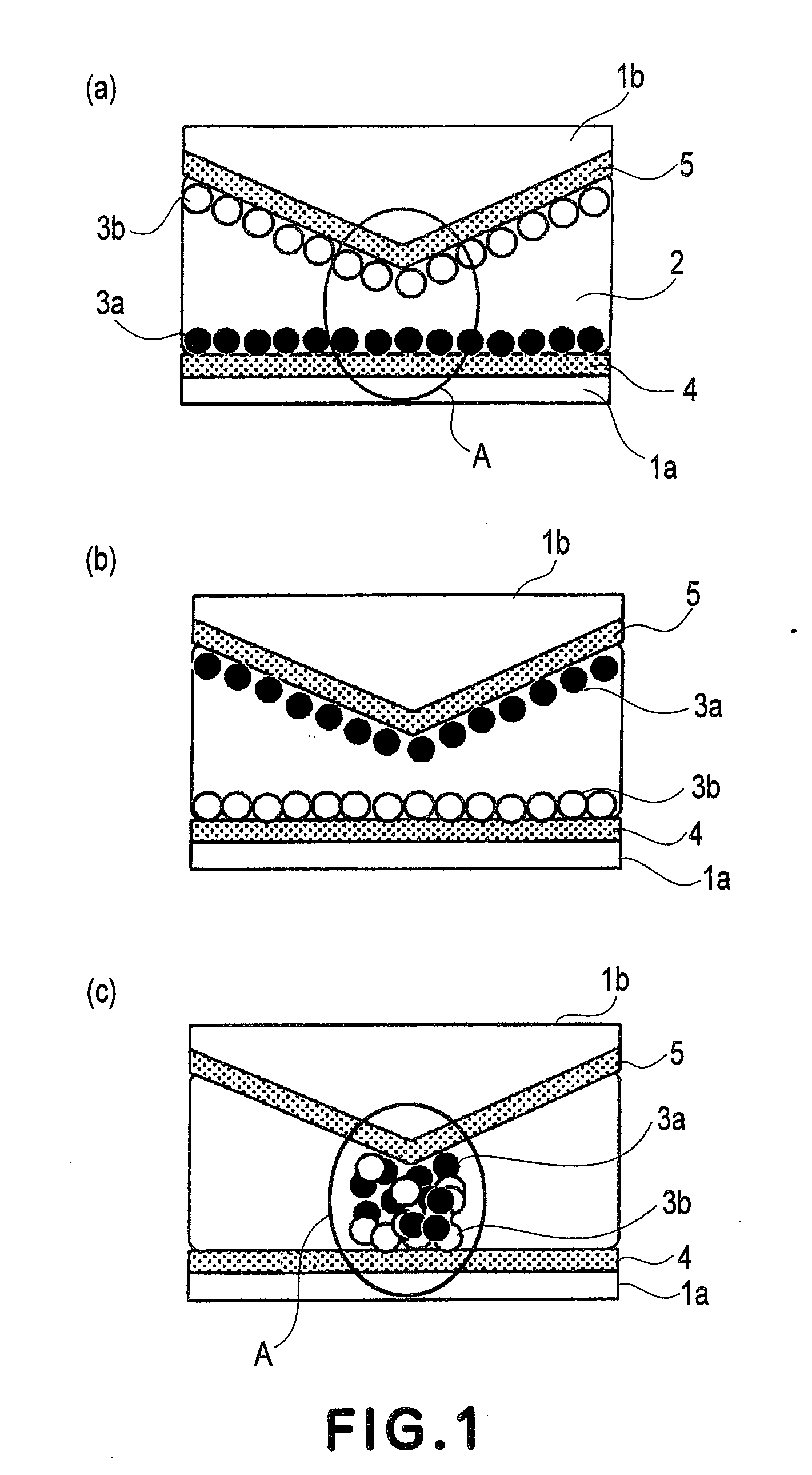
[0068]FIGS. 1(a) to 1(c) are schematic structural views of electrophoretic display apparatus according to this embodiment of the present invention. In FIG. 1, the electrophoretic display apparatus includes a first substrate 1a and a second substrate 1b which is disposed on a display side with a predetermined spacing between it and the first substrate 1a.

[0069]In a dispersion medium 2 filled in a closed container formed between the first substrate 1a and the second substrate 1b, (electrophoretic) migration particles of two types (first particles 3a and second particles 3b) having mutually different charge polarities and colors are dispersed. On the first substrate 1a, a first electrode 4 is formed and on the second substrate 1b, a second electrode 5 is formed. In this embodiment, as the first particles 3a, positively charged black particles are used and as the second particles 3b, negatively charged white particles are used. Further, the first electrode 4 is colored red.

[0070]Here, ...

second embodiment

[0092]Next, Second Embodiment of the present invention will be described.

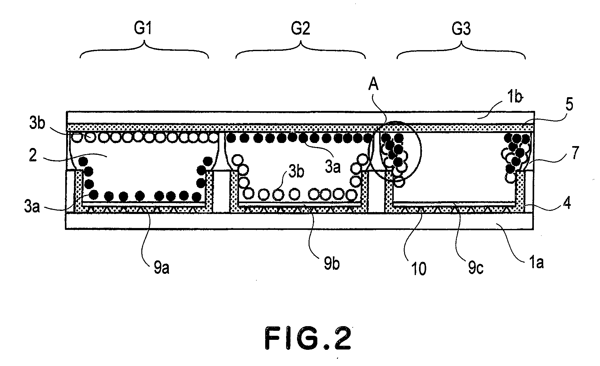
[0093]FIG. 2 is a schematic structural view of an electrophoretic display device provided in an electrophoretic display apparatus capable of effecting color display according to this embodiment. In FIG. 2, members or portions indicated by the same reference numerals as in FIGS. 1(a) to 1(c) represent the same or corresponding members or portions.

[0094]Referring to FIG. 2, a first pixel G1, a second pixel G2, and a third pixel G3 are disposed in parallel to constitute one pixel. A partition wall 7 is disposed between a first substrate 1a and a second substrate 1b so as to hold a constant spacing therebetween and partitions each of three pixels G1, G2 and G3. In each of closed containers defined by the substrates 1a and 1b and the partition wall 7, migration particles (first particles 3a and second particles 3b) of two types having different charge polarities and colors and a dispersion medium 2 are filled and se...

third embodiment

[0113]Next, Third Embodiment of the present invention will be described.

[0114]FIG. 4 is a schematic structural view of an electrophoretic display device provided in an electrophoretic display apparatus capable of effecting color display according to this embodiment. In FIG. 4, members or portions indicated by the same reference numerals as in FIG. 2 represent the same or corresponding members or portions.

[0115]Referring to FIG. 4, transparent microcapsules 8 each containing migration particles (first particles 3a and second particles 3b) of two types having different charge polarities and colors and a dispersion medium 2 are disposed between a first substrate 1a and a second substrate 1b. In this embodiment, each closed container is constituted by a microcapsule.

[0116]In this embodiment, as shown in FIG. 4, a part of a second electrode 5 is extended and formed along the surface of microcapsule so as to be close to a first electrode 4 side. By doing so, a distance between the first e...


PUM

PropertyMeasurementUnit
DC voltageaaaaaaaaaa
relative dielectric constantaaaaaaaaaa

Abstract

A display apparatus includes a first substrate provided with a plurality of closed containers, a fluid filled in the closed containers, a plurality of positively charged particles which have a relative dielectric constant different from the fluid and are dispersed and held in the fluid, a plurality of negatively charged particles which have a same color as the positively charged particles and a relative dielectric constant different from the fluid and are dispersed and held in the fluid, and a pair of electrodes for generating an electric field in the closed containers. The display apparatus displays an image formed by a positional distribution of positively and negatively charged particles in each of the closed containers.

Description

FIELD OF THE INVENTION AND RELATED ART[0001]The present invention relates to a display apparatus, such as an electrophoretic display apparatus which effects display on the basis of movement of (electrophoretic) migration particles, and a driving method of the display apparatus.[0002]In recent years, an amount of information which an individual can deal with has been significantly measured due to a remarkable advance of digital technology. In connection with this, development of display as information output means has been performed actively, so that technological innovation for displays of high usabilities, such as high definition, low power consumption, light weight, thin shape, etc., has been continued. Particularly, in recent times, a high-definition display which is easy to read and has a display quality equivalent to printed matter has been desired. The display of this type is a technique indispensable to a next-generation product, such as electronic paper, electronic book, etc...

Claims


Application Information

Patent Timeline
Patent Type & Authority Applications(United States)
IPC IPC(8): G09G3/34G02B26/00G02F1/167G02F1/17G09F9/37
CPCG09F9/372
Inventor MATSUDA, YOJIRO
Owner CANON KK
Why Eureka
Try Eureka