Optical waveguide device

a waveguide and optical waveguide technology, applied in the field of optical waveguide devices, can solve problems such as deterioration of alignment accuracy, and achieve the effect of maintaining alignment accuracy of optical fiber lines

Inactive Publication Date: 2008-12-25
MITSUMI ELECTRIC CO LTD
View PDF4 Cites 3 Cited by
  • Summary
  • Abstract
  • Description
  • Claims
  • Application Information

AI Technical Summary

Benefits of technology

[0012]It is, therefore, a main object of the present invention to provide an optical waveguide device to maintain alignment accuracy of an optical fiber line.

Problems solved by technology

However, there is a problem that when UV curable resin is supplied more than necessary, the UV curable resin flows into the rectangular groove, and thus when the UV curable resin cures and contracts, the end of the optical fiber line moves causing deterioration of alignment accuracy.

Method used


Image

  • Optical waveguide device
  • Optical waveguide device
  • Optical waveguide device

Examples


first embodiment

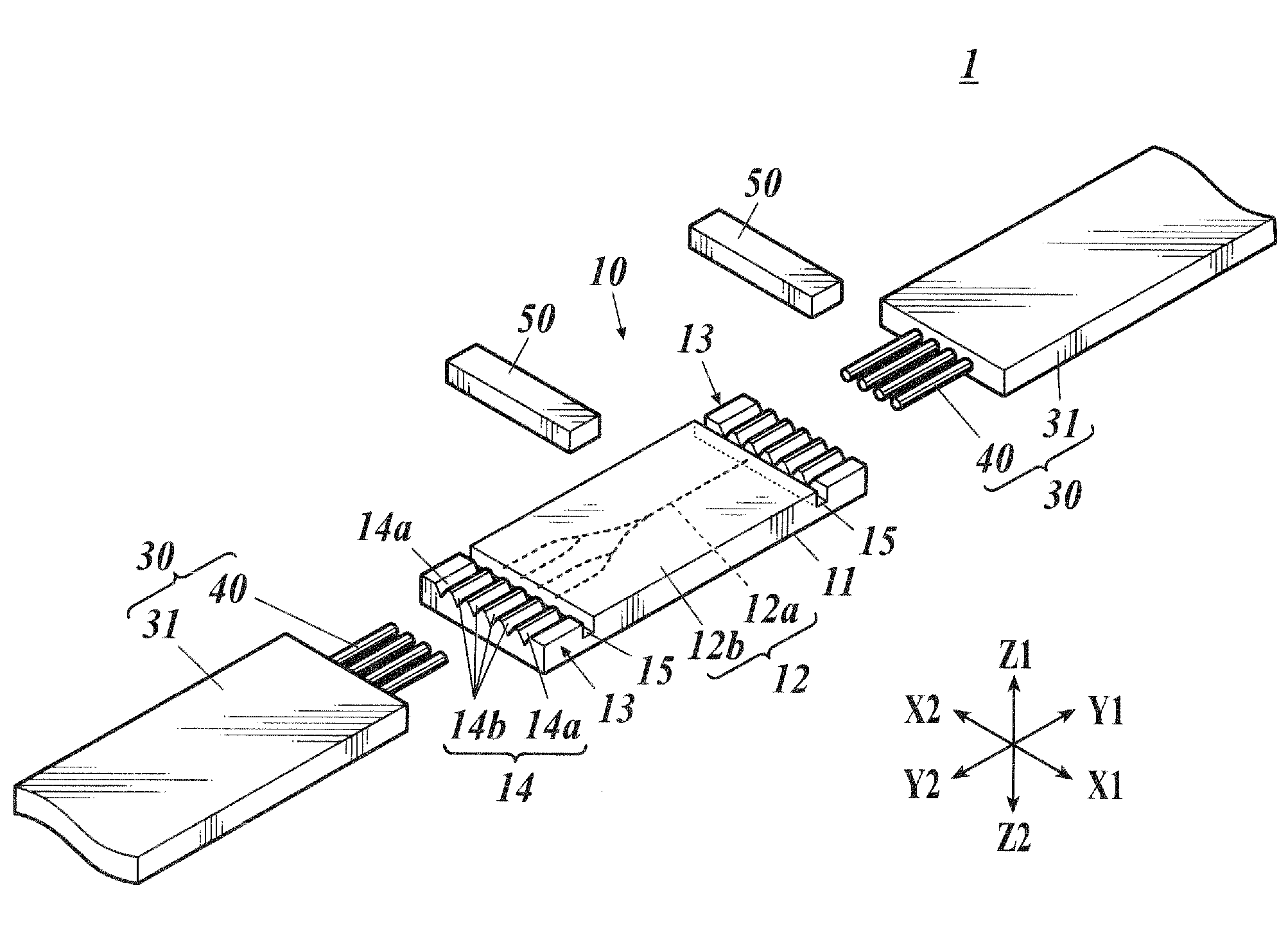
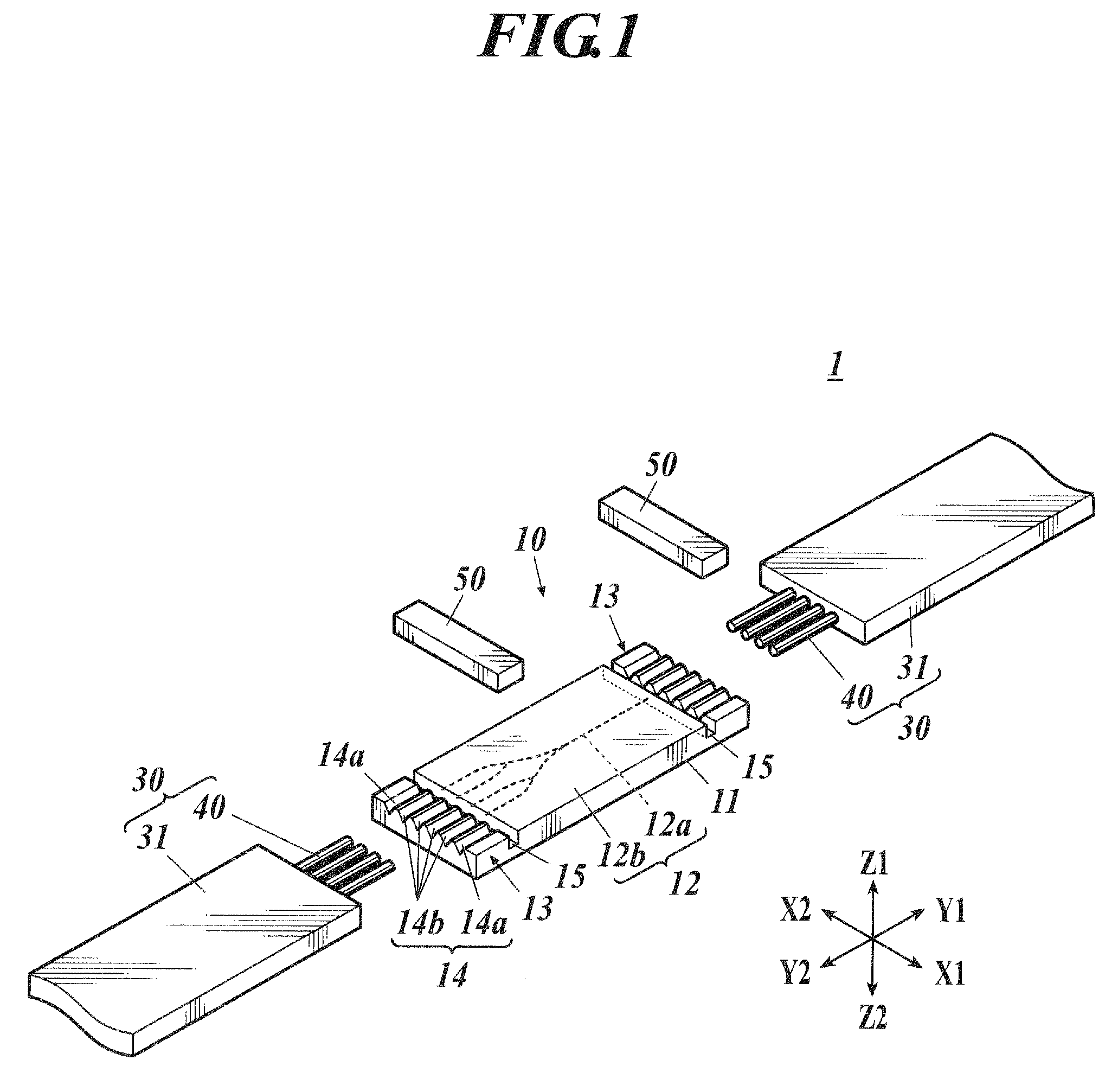
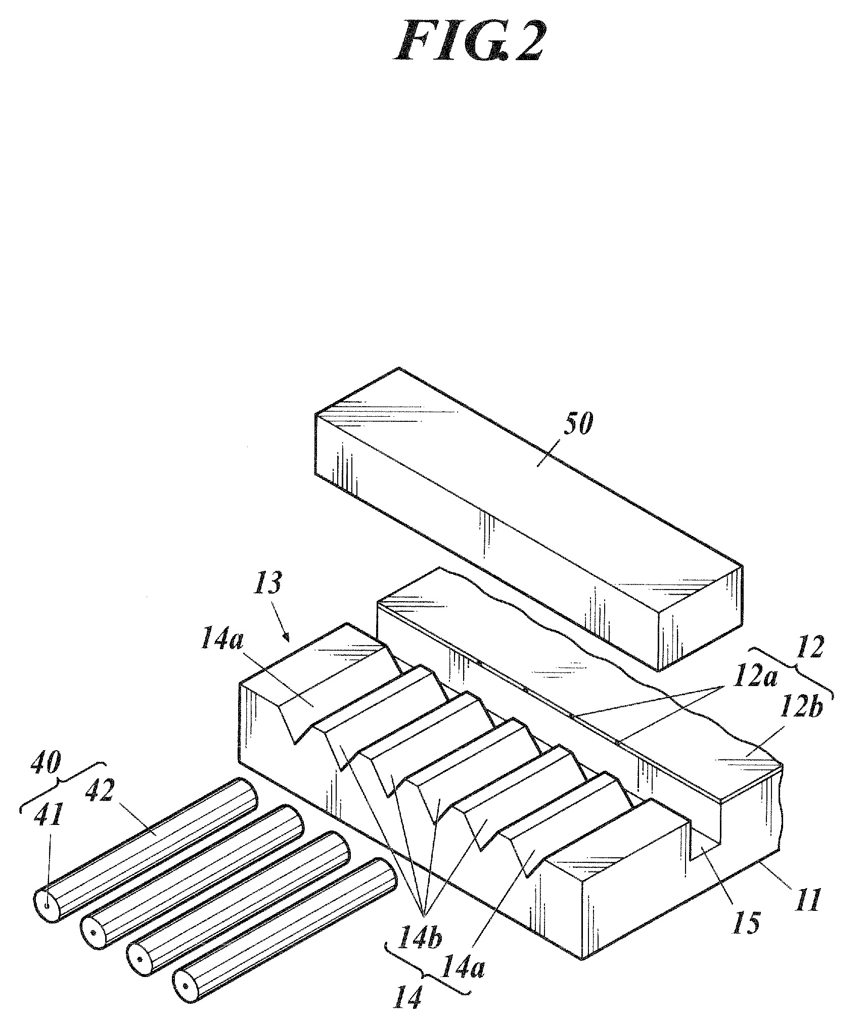
[0074]V-grooves and a rectangular groove were formed on an optical waveguide chip with an optical waveguide section including cores with eight ports.

[0075]A length of a connecting section (length of the V-groove) was 7 mm and a width of the V-groove was 127 μm.

[0076]A diameter of the optical fiber line was 250 μm.

[0077]A width of the rectangular groove was 460 μm and a depth was 250 μm.

[0078]A length of the glass block was 5 mm and a thickness was 1 mm.

[0079]The glass block was placed with the face of the glass block at the side of the optical waveguide section protruding 200 μm toward the optical waveguide section. As matching adhesive, 2 μL of UV curable resin with a viscosity of 450 CP was injected with a microsyringe from the optical waveguide section side of the glass block in a gap between the bottom face of the glass block and the top face of the optical waveguide section and the resin was cured with ultraviolet irradiation.

[0080]Also, reinforcement adhesive with a viscosity ...


PUM


Abstract

An optical waveguide device, including: a substrate including an optical waveguide and a connecting section formed on at least one end of the optical waveguide; an optical fiber placed in the connecting section and optically connected to the optical waveguide; and a fixing member to nip the optical fiber between the connecting section and the fixing member; wherein on the substrate, a groove is formed between the optical waveguide and the connecting section; and the fixing member is provided across the groove

Description

BACKGROUND OF THE INVENTION[0001]1. Field of the Invention[0002]The present invention relates to an optical waveguide device connected to an optical cable.[0003]2. Description of Related Art[0004]In recent years, with the increase in speed of data communication, optical communication using optical cables is replacing communication using metallic cables and becoming the main stream. As an optical waveguide device which performs optical communication, there is an optical waveguide device optically connected to an optical cable and the device splits the light transmitted from the optical cable into a plurality of optical cables.[0005]An optical waveguide device comprises an optical waveguide section including a core formed with a plurality of branches in a Y-shape and a clad formed so as to enwrap the core, and a connecting section to fix optical fiber lines and to connect the optical fiber lines to both ends of the core, and the optical waveguide section and the connecting section are...

Claims


Application Information

Patent Timeline
Patent Type & Authority Applications(United States)
IPC IPC(8): G02B6/38
CPCG02B6/30G02B6/36G02B6/3636G02B6/3652
Inventor SATO, KOKI
Owner MITSUMI ELECTRIC CO LTD
Why Eureka
Try Eureka