Corrugated tube

Active Publication Date: 2009-01-01
YAZAKI CORP
View PDF24 Cites 23 Cited by
  • Summary
  • Abstract
  • Description
  • Claims
  • Application Information

AI Technical Summary

Benefits of technology

[0035]With the construction described above, since the pair of the ribs is symmetrically arranged in the height direction of the rib, therefore the bendi

Problems solved by technology

However, the corrugated tube 61 shown in FIG. 8 canno

Method used


Image

  • Corrugated tube
  • Corrugated tube
  • Corrugated tube

Examples


Example

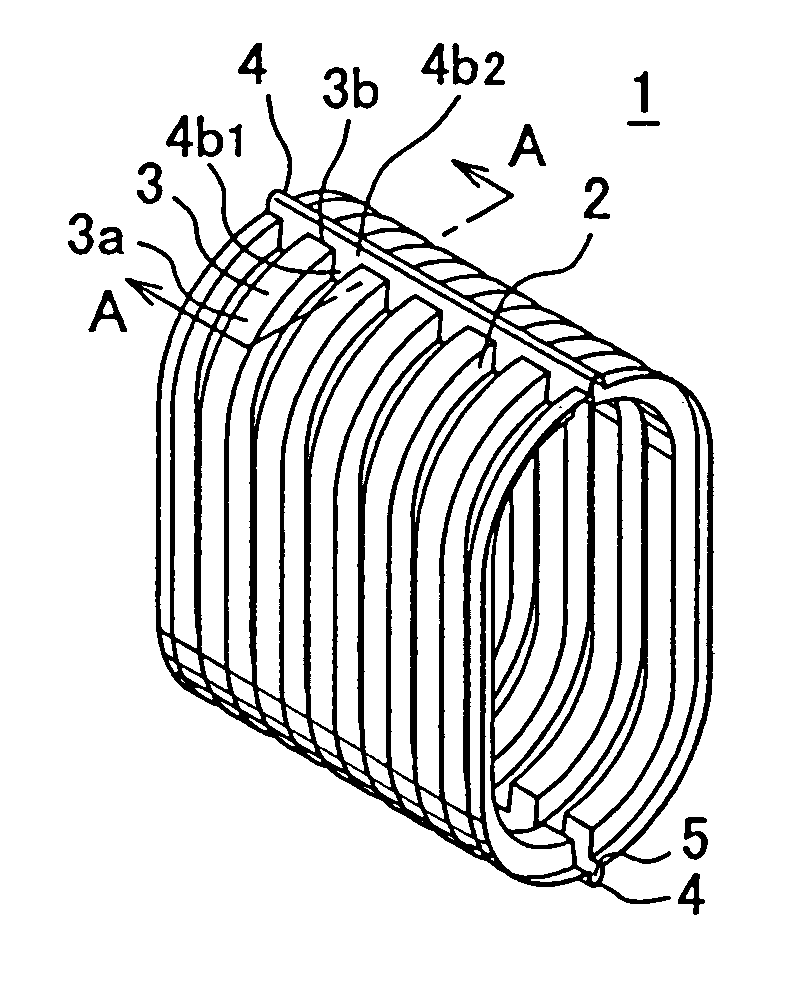
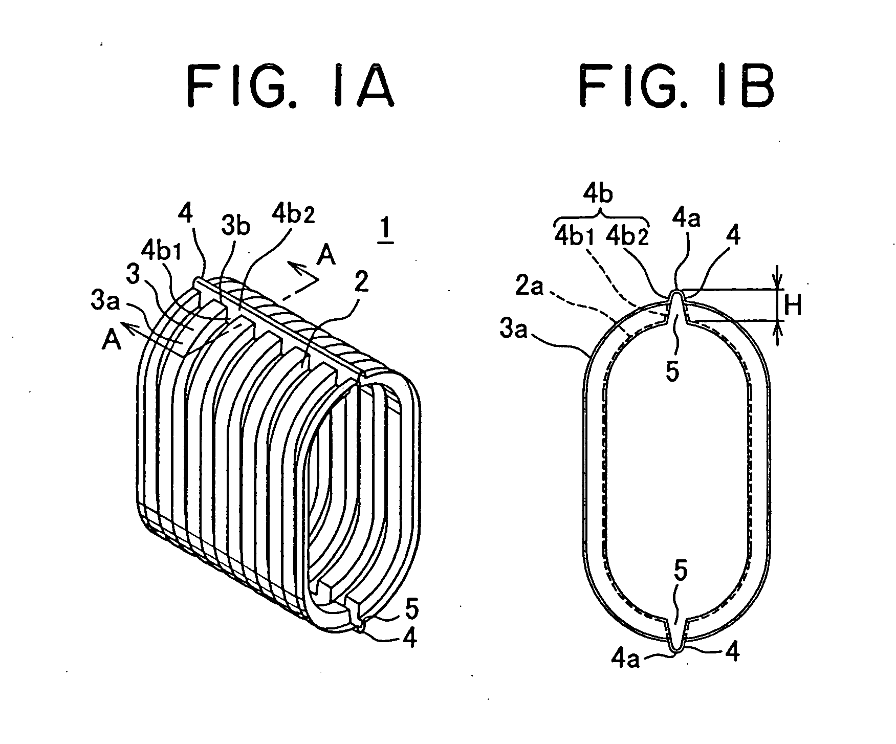
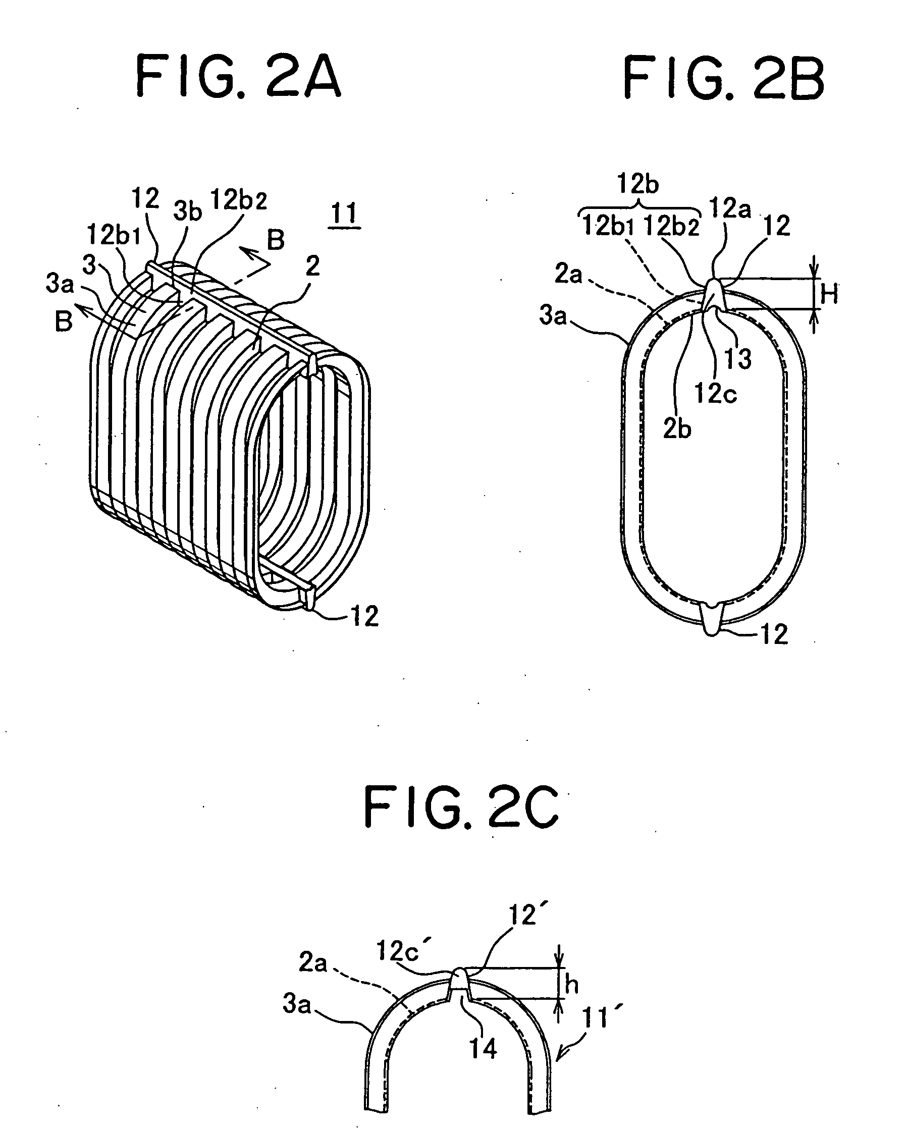
[0050]FIGS. 1A and 1B show the first preferred embodiment of a corrugated tube according to the present invention.

[0051]The corrugated tube 1 is made of synthetic resin and includes dented grooves (i.e. valley parts) 2 and projecting strips (i.e. mountain parts) 3 on an outer periphery thereof, which are arranged alternately in a longitudinal direction of the corrugated tube 1, and has an elliptic shape in section, wherein at both end parts situated on a long diameter-side of the elliptic shape, a rib 4 is integrally formed projecting from an outer peripheral surface (i.e. bottom surface) 2a of the valley part 2 and extending beyond an outer peripheral surface (i.e. top surface) of the mountain part 3, and the inside of the rib 4 is made hollow (a corresponding hollow part being denoted by a reference numeral 5).

[0052]In comparison with the conventional example shown in FIG. 8, in the conventional example the top of the rib is flush with the top surface of the mountain part, on the ...


PUM


Abstract

A corrugated tube is provided, which can easily bend a wiring harness in one direction and can make the wiring harness hardly bend in another direction crossing the one direction at right angles, wherein the wiring harness is made further hardly bend in the other direction, so that the slack of the wiring harness for use in supplying electric power to a slide door can be effectively prevented from occurring. The corrugated tube includes: dented grooves and projecting strips formed on an outer periphery of the corrugated tube and arranged alternately in a longitudinal direction of the corrugated tube; and a reinforcing rib formed projecting from an outer peripheral surface of the dented groove and extending beyond an outer peripheral surface of the projecting strip, the reinforcing rib being formed in the longitudinal direction of the corrugated tube.

Description

BACKGROUND OF THE INVENTION[0001](1) Field of the Invention[0002]The present invention relates to a bellows-shaped corrugated tube as a harness-protecting tube, through which an electric wire passes being bent, for supplying electric power to a slide door, slide seat or the like of a motor vehicle.[0003](2) Description of the Related Art[0004]FIGS. 6 and 7 shows an example of a harness wiring structure using a conventional corrugated tube (for example, see Japanese Patent Application Laid-Open No. 2001-354085).[0005]The harness wiring structure is for mounting a wiring harness 43 from a slide door 41 of a motor vehicle to a vehicle body 47 so as to supply electric power to electric equipment and auxiliary equipment located on the side of slide door. An outer periphery of the wiring harness 43 is equipped with a corrugated tube 43b made of synthetic resin so as to safely protect a plurality of electric wires 43a from interference with the outside. The corrugated tube 43b includes den...

Claims


Application Information

Patent Timeline
IPC IPC(8): F16L11/11
CPCF16L3/26F16L7/00H02G3/0468F16L11/15F16L11/115
Inventor KISU, NAOMINISHIJIMA, MASATAKA
Owner YAZAKI CORP
Why Eureka
Try Eureka