Method For Producing a Hole

Inactive Publication Date: 2009-01-01
SIEMENS AG
View PDF5 Cites 27 Cited by
  • Summary
  • Abstract
  • Description
  • Claims
  • Application Information

AI Technical Summary

Benefits of technology

[0017]More rapid production of the hole in a component is made possible by the subdivision of a hole during production into a lower region a

Problems solved by technology

The use of such ultrashort laser pulses is expensive an

Method used


Image

  • Method For Producing a Hole
  • Method For Producing a Hole
  • Method For Producing a Hole

Examples


Embodiment Construction

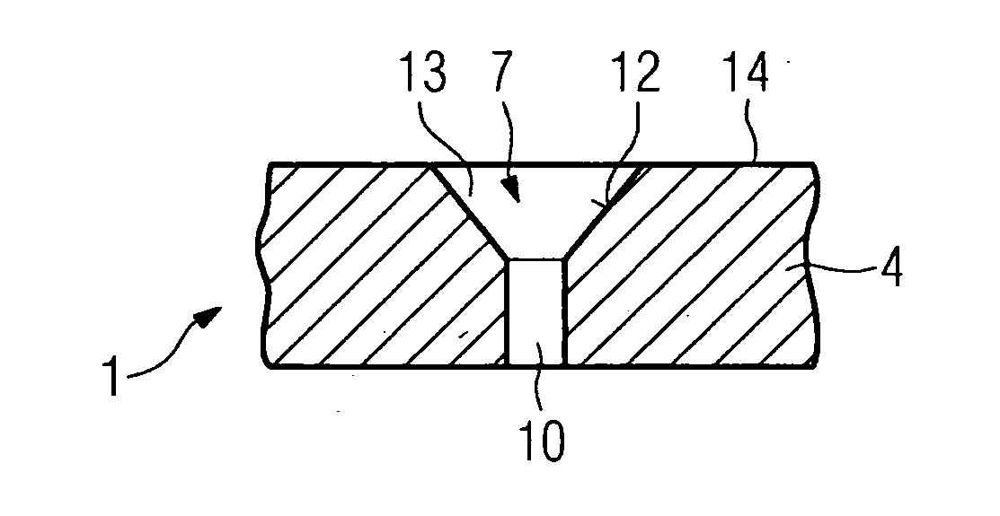
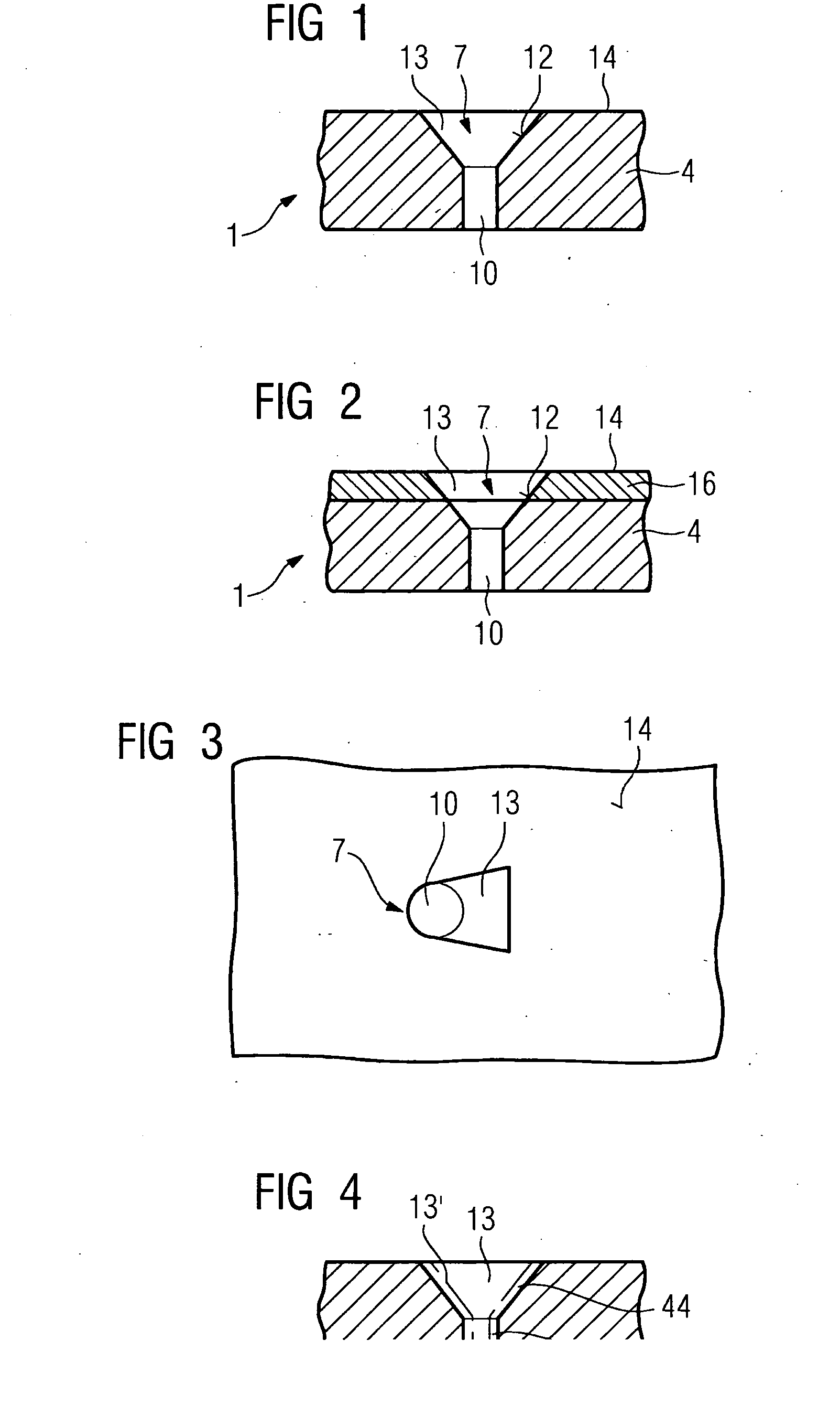
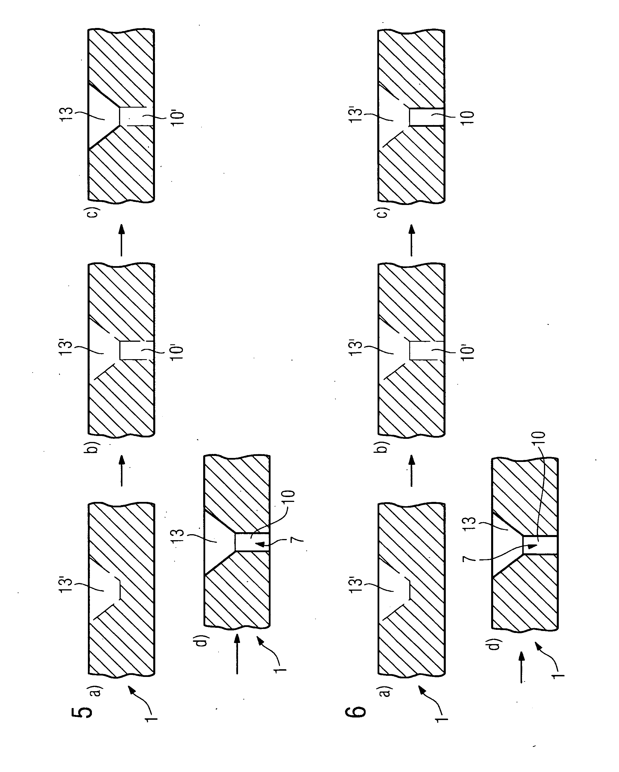
[0027]Description of the Component with a Hole FIG. 1 shows a component 1 with a hole 7. The component 1 consists of a substrate 4 (for example a casting or DS or SX component).

[0028]The substrate 4 may be metallic and / or ceramic. Particularly in the case of turbine components, for example turbine rotor blades 120 or guide vanes 130 (FIGS. 11, 12), heat shield elements 155 (FIG. 13) and other housing parts of a steam or gas turbine 100 (FIG. 11), but also an aircraft turbine, the substrate 4 consists of a nickel-, cobalt- or iron-based superalloy. In the case of turbine blades for aircraft, the substrate 4 consists for example of titanium or a titanium-based alloy.

[0029]The substrate 4 comprises a hole 7, which is for example a through-hole. It may however also be a blind hole. The hole 7 consists of a lower region 10 which starts from an inner side of the component 1 and is for example designed symmetrically (for example circularly, ovally or rectangularly), and an upper region 13 ...


PUM

PropertyMeasurementUnit
Timeaaaaaaaaaa
Lengthaaaaaaaaaa

Abstract

There are a multiplicity of methods of making through-holes. In particular in the production of a multiplicity of film-cooling holes, as in gas turbine blades or combustion chamber elements, small time advantages are also important when making a hole. The method according to the invention, to make the hole close to the final contour in each case in sections in a top and a bottom region in order to then produce the final contour with other laser parameters, achieves time advantages.

Description

CROSS REFERENCE TO RELATED APPLICATIONS[0001]This application is the US National Stage of International Application No. PCT / EP2006 / 070280, filed Dec. 29, 2006 and claims the benefit thereof. The International Application claims the benefits of European application No. 06000406.6 filed Jan. 10, 2006, both of the applications are incorporated by reference herein in their entirety.FIELD OF INVENTION[0002]The invention relates to a method for producing a hole as claimed in the claims.BACKGROUND OF THE INVENTION[0003]For many components, castings in particular, material removal subsequently needs to be carried out for instance to form indentations or through-holes need. Particularly for turbine components which have film cooling holes for cooling, holes are subsequently introduced after production of the component.[0004]Such turbine components often also have layers, for example a metallic layer or interlayer and / or a ceramic outer layer. The film cooling holes must then be produced thro...

Claims


Application Information

Patent Timeline
IPC IPC(8): B23K26/00
CPCB23K26/383B23K26/388B23K2201/001F01D5/186Y10T29/49341Y02T50/676F05D2230/13B23K15/085Y02T50/67B23K26/384B23K26/389B23K2101/001Y02T50/60
Inventor BECK, THOMASCOX, NIGEL-PHILIPSETTEGAST, SILKE
Owner SIEMENS AG
Why Eureka
Try Eureka