Hybrid laser scanning and imaging reader

a laser scanning and imaging reader technology, applied in the field of hybrid laser scanning and imaging readers, can solve the problems of inability to read other two-dimensional symbols at all, the reader is too big and bulky to pick up and aim at symbols easily, and the laser beam-based reader is too big and bulky to achieve the effect of easy reading of wide targets, excellent and intuitive “aim and shoot”

Active Publication Date: 2009-01-01
SYMBOL TECH LLC
View PDF8 Cites 35 Cited by
  • Summary
  • Abstract
  • Description
  • Claims
  • Application Information

AI Technical Summary

Benefits of technology

[0015]In accordance with one aspect of this invention, a controller, especially but not necessarily operative for decoding the digital signal, is operatively connected to the modules, for preventing reading interference between the modules during reading. For example, a mode sensor is employed for detecting the mode of operation; and the controller enables the laser scanning module to read the indicia when the mode sensor detects the handheld mode, and enables the imaging module to read the indicia when the mode sensor detects the hands-free mode. The mode sensor is operative for detecting the mode of operation by sensing one of motion, position and orientation of the housing.
[0033]Hence, this invention proposes a hybrid, dual module, reader that can be used as a presentation or swipe reader for hands-free reading of one- or two-dimensional symbols, and also offers excellent and intuitive “aim-and-shoot” ergonomics for handheld reading of one- or two-dimensional symbols by providing a gun-shaped housing having a trigger to be depressed by the operator's forefinger. The reader gives a clear visual indication of the extent of its field of view, to facilitate reading of wide targets like driver's licenses and two-dimensional symbols in either the hands-free or handheld mode. In addition, the working distance range increases in the handheld mode as compared to the hands-free mode.

Problems solved by technology

Although the moving laser beam-based reader and the imager-based reader are generally satisfactory for their intended purposes, their capabilities are limited in certain respects.
The moving laser beam-based reader works well in the handheld mode when reading one-dimensional symbols, but does not read certain two-dimensional symbols as well as the imager-based reader can, and cannot read other two-dimensional symbols at all.
Sometimes, the moving laser beam-based reader is too big and bulky to pick up and aim at a symbol easily.
The imager-based reader, on the other hand, works well in the hands-free mode for reading one- and two-dimensional symbols, but it works poorly in the handheld mode primarily due to its housing design, which fails ergonomically in several ways.
This is an uncomfortable grip.
If the switch is not pressed before aiming the reader at a symbol, the reader will scan the symbol automatically; however, this leaves open the possibility of accidentally reading the wrong symbol as the reader is moved towards the desired symbol to be read.
Accidental reads waste time and open the possibility of erroneously charging customers at point-of-sale workstations, or of inaccurately recording scanned inventory information, etc.
Another problem with the known imager-based readers is that the aiming spot only indicates where a center of the imager's field of view is.
This is a significant handicap when reading wide symbols, and particularly when reading the two-dimensional symbols on the back of driver's licenses in most states of the United States.
If the symbol is held further away, the imager does not have adequate resolution to read some symbols and, if the symbol is held closer, then the field of view will not cover the entire symbol, thereby rendering the symbol unreadable.
This is a slow process and not acceptable for busy scanning environments.
Another problem that the known imager-based reader fails to address is that, when used in the hands-free mode, the reader needs to have a somewhat limited working range (around six to eight inches), or the reader will accidentally scan products that customers place on the counter-top nearby.

Method used


Image

  • Hybrid laser scanning and imaging reader
  • Hybrid laser scanning and imaging reader
  • Hybrid laser scanning and imaging reader

Examples


Embodiment Construction

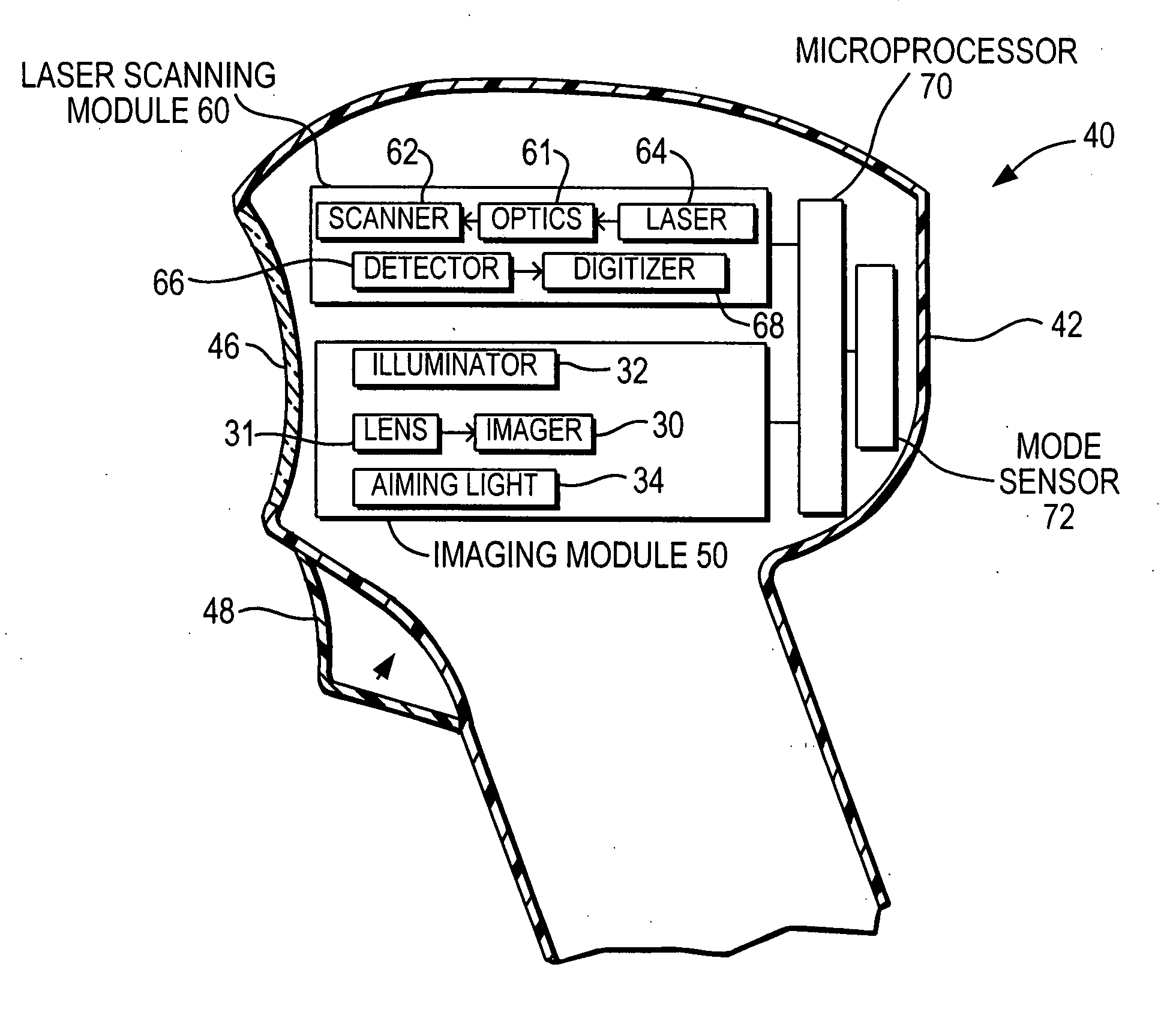
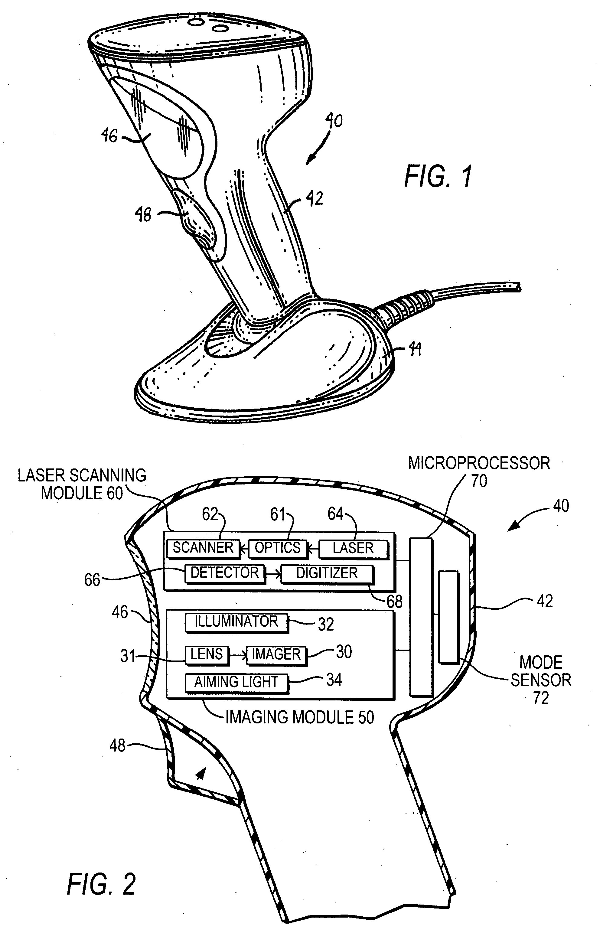
[0039]Reference numeral 40 in FIG. 1 generally identifies an electro-optical, portable reader having a gun-shaped housing 42 connected to a base 44. The base 44 rests on a countertop or analogous support surface and serves for supporting the reader 40. The reader 40 can thus be used in a hands-free mode as a stationary workstation in which products bearing indicia, such as one- or two-dimensional symbols, are presented to, or slid or swiped past, a presentation area or window 46. The gun-shaped housing 42 also has a handle that can be picked up by an operator off the countertop and held in the operator's hand in a handheld mode. A trigger 48 is located on the gun-shaped housing 42 at a location underlying an operator's forefinger when the operator holds the handle in the operator's hand in the handheld mode. The trigger 48 is manually depressed to initiate reading of the symbol. The handle is permanently and pivotably connected to the base 44 in both the handheld and hands-free mode...


PUM


Abstract

An imaging module is supported by a housing of a reader for electro-optically reading indicia. The imaging module includes a solid-state imager having an array of image sensors for capturing return light from the indicia during reading. A laser scanning module is also supported by the housing and includes a scanner for scanning at least one of a laser beam from a laser and a field of view of a light detector in a scan pattern across the indicia during reading. A controller is operatively connected to the modules, and is operative for preventing reading interference between the modules during reading.

Description

DESCRIPTION OF THE RELATED ART[0001]Moving laser beam-based readers, in both handheld and hands-free modes of operation, have been used to electro-optically read coded symbols, particularly one-dimensional Universal Product Code (UPC) type symbols, in supermarkets, warehouse clubs, department stores, and other kinds of retailers for many years. A laser generates a laser beam directed to a symbol associated with a product for reflection and scattering from the symbol. A detector having a field of view detects light of variable intensity returning from the symbol. A scanner scans at least one of the laser beam and the field of view in a scan pattern comprised of one or more scan lines. When at least one of the scan lines sweeps over the symbol, an electrical signal indicative of the intensity of the detected return light is processed by signal processing circuitry including a microprocessor; the symbol is read; and the product is identified.[0002]Imager-based readers, in both handheld...

Claims


Application Information

Patent Timeline
Patent Type & Authority Applications(United States)
IPC IPC(8): G06K7/10
CPCG06K7/10554G06K7/10712G06K2207/1011G06K7/1096G06K7/109
Inventor CARLSON, BRADLEYBARKAN, EDWARDGUREVICH, VLADIMIRBROCK, CHRISTOPHER WARREN
Owner SYMBOL TECH LLC
Why Eureka
Try Eureka