Dichroic Filter

Inactive Publication Date: 2009-01-01
NIKON CORP
View PDF1 Cites 33 Cited by
  • Summary
  • Abstract
  • Description
  • Claims
  • Application Information

AI Technical Summary

Benefits of technology

[0014]According to the present invention, it is possible to provide a dichroic filter that

Problems solved by technology

However, the 1,310 nm light impinges the dichroic filter at a prescribed angle and is reflected thereby, and that ref

Method used


Image

  • Dichroic Filter
  • Dichroic Filter
  • Dichroic Filter

Examples


working examples

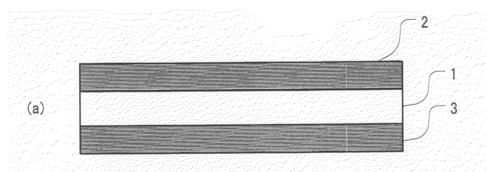
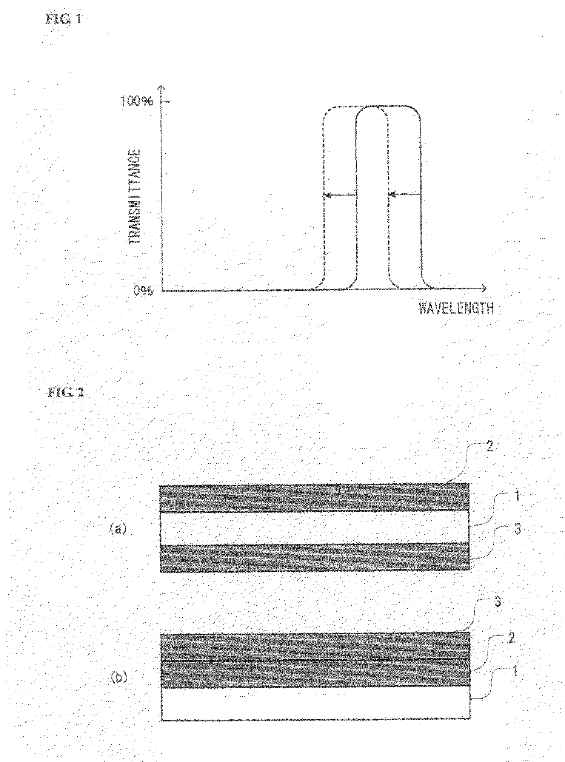
[0041]A dichroic filter was prepared by sequentially layering a low pass filter, which was formed by alternately layering SiO2 (a low-refractive-index substance) and Nb2O5 (a high-refractive-index substance), an adjustment layer, and a high pass filter, which was formed by alternately layering SiO2 (a low-refractive-index substance) and Nb2O5 (a high-refractive-index substance), on a glass substrate.

[0042]The low pass filter was prepared by: first forming a film of SiO2 on the surface of the glass substrate with a thickness of 239.1 nm (optical film thickness of 346.7 nm); layering 29 layers thereon, wherein each layer comprised a pair of films, i.e., an Nb2O5 film and an SiO2 film (the Nb2O5 film had a thickness of 62.5 nm and an optical film thickness of 138.8 nm, and the SiO2 film had a thickness of 478.1 nm and an optical film thickness of 693.); and then layering thereon one layer of an Nb2O5 film with a thickness of 62.5 nm and an optical film thickness of 138.8 nm. The adjust...


PUM


Abstract

A first multilayer film filter 2 is formed on one side of a transparent substrate 1, e.g., glass, and a second multilayer film filter 3 is formed on the other side. The multilayer film filter 2 is a low pass filter, and the multilayer film filter 3 is a high pass filter. Furthermore, the multilayer films are designed so that a shift in spectral transmittance characteristics produced by changes in incident angle is larger for the multilayer film filter 2 than for the multilayer film filter 3. Thereby, even if light of a wavelength that should be blocked is transmitted due to the shift in the spectral transmittance characteristics of the multilayer film filter 2, the transmittance of light of that wavelength is blocked because of the shift in the spectral transmittance characteristics of the multilayer film filter 3. Thereby, the dichroic filter transmits a significantly reduced percentage of stray light that impinges at large incident angles.

Description

FIELD OF THE INVENTION[0001]The present invention relates to a dichroic filter.RELATED ART[0002]Dichroic filters are used in the field of, for example, optical communications for the purpose of transmitting light of a first wavelength and reflecting (without transmitting) light of a second wavelength. For example, with a dichroic filter that is designed to, for example, transmit light with a wavelength of 1,560 nm and reflect (without transmitting) light with a wavelength of 1,310 nm, the 1,560 nm light that emerges from an optical fiber enters the dichroic filter perpendicularly and transmits therethrough, and the 1,310 nm light that emerges from a separate light source is reflected by the same dichroic filter and enters the optical fiber.[0003]In an optical system of the type discussed above, the 1,560 nm light enters the dichroic filter perpendicularly and is transmitted therethrough with high transmittance, and therefore the amount of the stray light is small, which makes it unn...

Claims


Application Information

Patent Timeline
IPC IPC(8): G02B5/28
CPCG02B5/28G02B5/285G02B5/281
Inventor OKAMOTO, MIKIO
Owner NIKON CORP
Why Eureka
Try Eureka