Imaging apparatus

a technology of imaging apparatus and slit, which is applied in the field of imaging apparatus, can solve the problems of blurring and inability to distinguish, and achieve the effects of reducing the size of the imaging apparatus, reducing the cost, and improving the accuracy of distance measuremen

Inactive Publication Date: 2013-11-07
SOVEREIGN PEAK VENTURES LLC
View PDF7 Cites 19 Cited by
  • Summary
  • Abstract
  • Description
  • Claims
  • Application Information

AI Technical Summary

Benefits of technology

[0008]However, with the above-described conventional technologies, it is required to, for example, reduce the size of the imaging apparatus, decrease the cost, and improve the distance measuring precision. A non-limiting illustrative embodiment of the present application provides a compact imaging apparatus capable of measuring a distance with high precision.

Problems solved by technology

However, with a single image, it cannot be distinguished whether the blur is a pattern of the subject itself or the blur occurs because of the subject distance.

Method used


Image

  • Imaging apparatus
  • Imaging apparatus
  • Imaging apparatus

Examples


embodiment 1

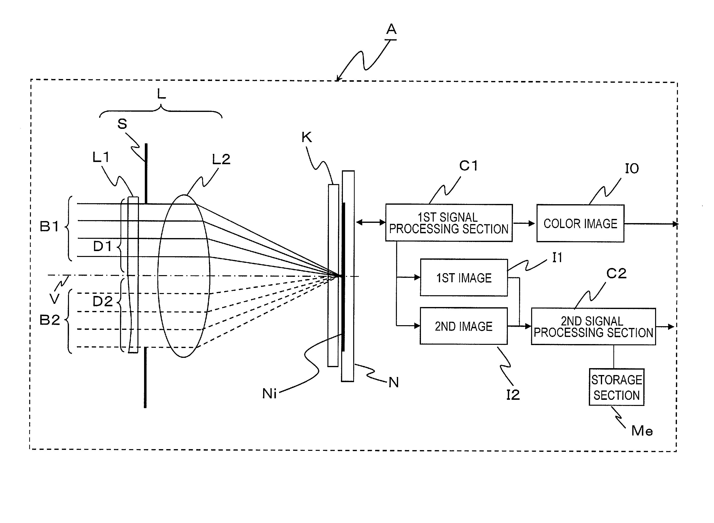
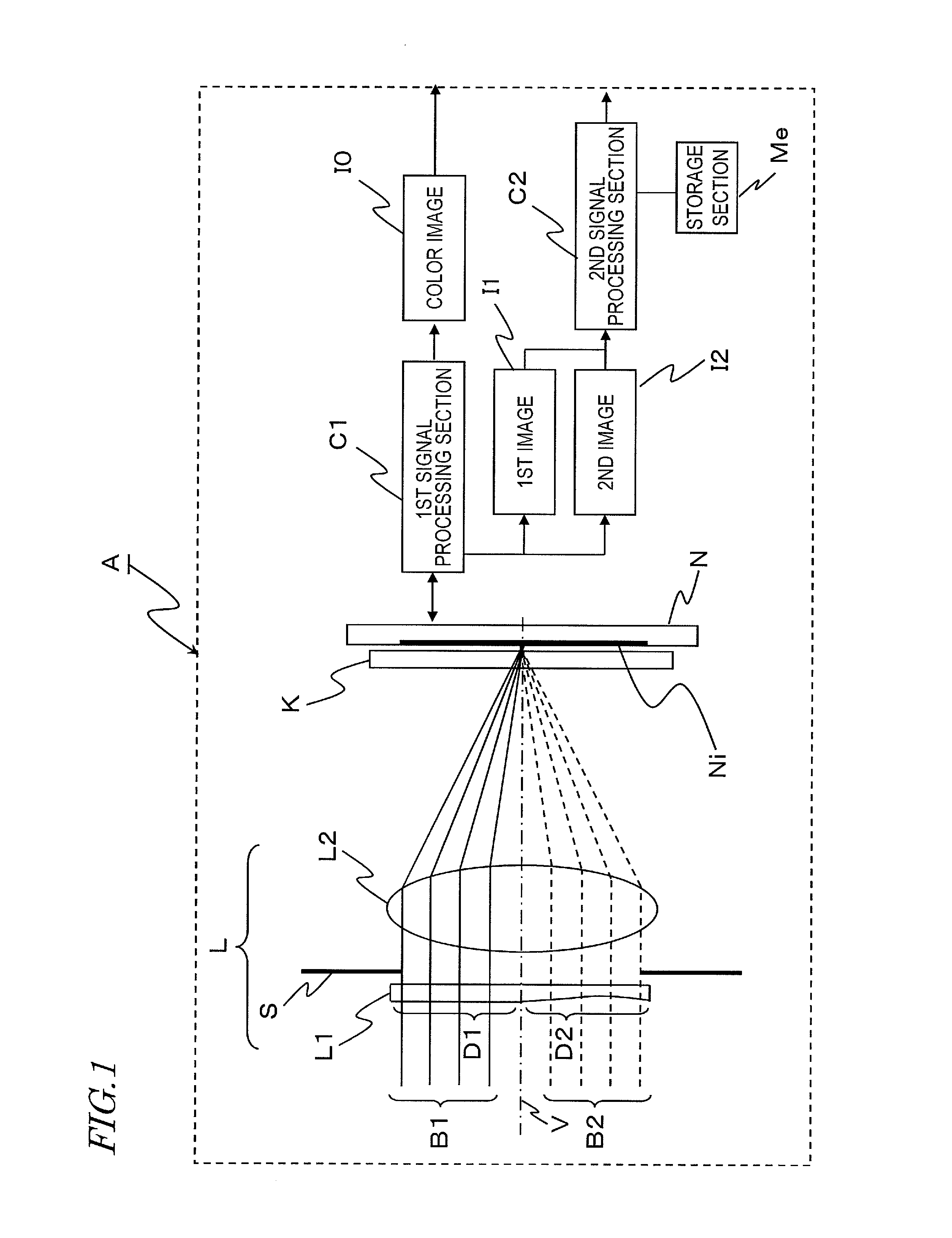
[0112]FIG. 1 is a schematic view showing an imaging apparatus A in Embodiment 1. The imaging apparatus A in Embodiment 1 includes a lens optical system L having an optical axis V, an optical array element K located in the vicinity of the focal point of the lens optical system L, an imaging element N, a first signal processing section C1, a second signal processing section C2, and a storage section Me.

[0113]The lens optical system L includes an optical element L1 on which light beams B1 and B2 from a subject (not shown) are incident, a stop S on which the light which has passed the optical element L1 is incident, and a lens L2 on which the light which has passed the stop S is incident. The optical element L1 includes an optical area D1 and an optical area D2 having an optical characteristic which provides a focusing characteristic different from the focusing characteristic by light rays which have passed the optical area D1. The optical element L1 may be located in the vicinity of th...

embodiment 2

[0181]In Embodiment 2, unlike in Embodiment 1, the optical areas of the optical element L1 have different sizes, and the optical array element includes microlenses instead of a lenticular lens. Herein, the same contents as those of Embodiment 1 will not be described in detail.

[0182]FIG. 11 is a front view of an optical element L1 as seen from the side of a subject. The optical element L1 is divided into the optical areas D1 and D2. The optical area D2 is further divided into optical areas d2A, d2B and d2C. As shown in FIG. 11, the optical areas D1, d2A, d2B and d2C are obtained by dividing a plane vertical to the optical axis V into four, namely, upper, lower, left and right areas along borders having the optical axis V as the center thereof. The optical areas D1 and D2 respectively have optical characteristics which provide different focusing characteristics by light rays which have passed the respective areas.

[0183]FIG. 12 is an isometric view of the optical array element K. At a ...

embodiment 3

[0207]In Embodiment 3, unlike in Embodiments 1 and 2, the lenticular lens or the microlens array are formed on the surface of the imaging plane. Herein, the same contents as those of Embodiment 1 will not be described in detail.

[0208]FIGS. 17A and 17B are enlarged views of the optical array element K and the imaging element N. In this embodiment, a lenticular lens (or a microlens array) Md is formed on the imaging plane Ni of the imaging element N. On the imaging plane Ni, the pixels P are arrayed in rows and columns like in Embodiment 1. One optical component of the lenticular lens or one optical component of the microlens array corresponds to a plurality of pixels P. In this embodiment also, like in Embodiments 1 and 2, the light beams which have passed different areas on the optical element L1 can be respectively guided to different pixels. FIG. 17B shows a modification of this embodiment. In the structure of FIG. 17B, the microlens array Ms is formed on the imaging plane Ni so a...


PUM


Abstract

An imaging apparatus disclosed in the present application includes a lens optical system, an imaging element and an optical array element. The lens optical system includes first and second areas having different optical characteristics with each other. The imaging element includes first and second pixels each including a filter of a first spectral transmittance characteristic, third pixels including a filter of a second spectral transmittance characteristic, and fourth pixels including a filter of a third spectral transmittance characteristic. The optical array element causes the light passing through the first area to be incident on the first pixels and one of the third and fourth pixels and causes the light passing through the second area to be incident on the second pixels and the other of third and fourth pixels.

Description

[0001]This is a continuation of International Application No. PCT / JP2012 / 007667, with an international filing date of Nov. 29, 2012, which claims priorities of Japanese Patent Application No. 2011-261593, filed on Nov. 30, 2011 and Japanese Patent Application No. 2011-274680, filed on Dec. 15, 2011, the contents of which are hereby incorporated by reference.BACKGROUND[0002]1. Technical Field[0003]The present application relates to an imaging apparatus such as a camera or the like.[0004]2. Description of the Related Art[0005]Recently, an inter-vehicle distance measurement for an automobile, an automatic focusing system of a camera, and a three-dimensional shape measuring system use a distance measuring device for measuring a distance to a subject (distance measuring target) by use of parallax between a plurality of imaging optical systems.[0006]In such a distance measuring device, a pair of imaging optical systems located in a left-right or up-down positional relationship form images...

Claims


Application Information

Patent Timeline
Patent Type & Authority Applications(United States)
IPC IPC(8): G01C3/08
CPCG01C3/08
Inventor IMAMURA, NORIHIROANDO, TAKAMASAKORENAGA, TSUGUHIRO
Owner SOVEREIGN PEAK VENTURES LLC
Why Eureka
Try Eureka