
Writing method for optical disk drive

a writing method and optical disk technology, applied in the field of optical disk drive writing method, can solve the problems of affecting the quality of optical disk drive, optical disk drive is not adjusted, and the overall efficiency of the operation is decreased or disabled

Inactive Publication Date: 2009-01-01
QUANTA STORAGE INC
View PDF2 Cites 5 Cited by
  • Summary
  • Abstract
  • Description
  • Claims
  • Application Information

AI Technical Summary

Benefits of technology

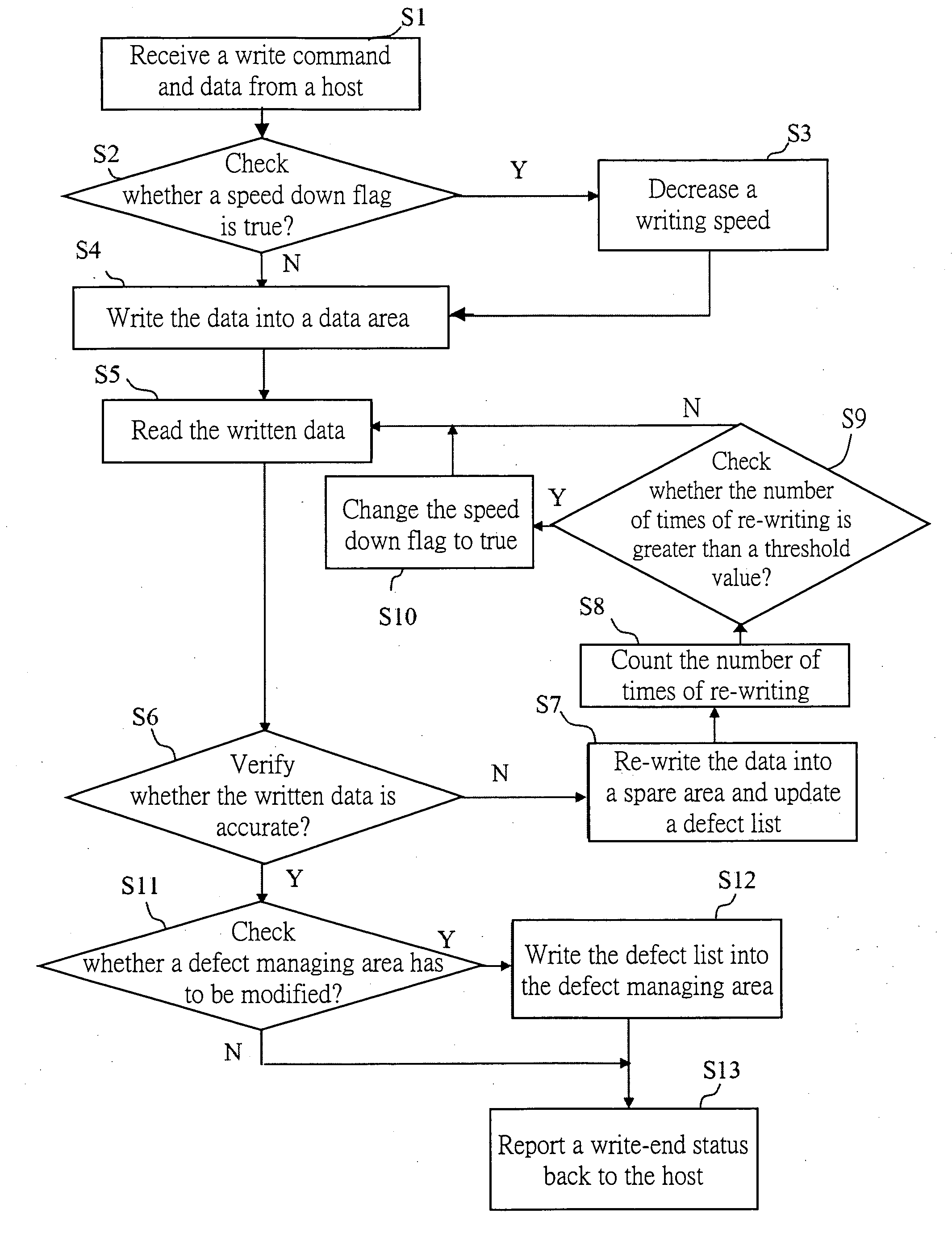
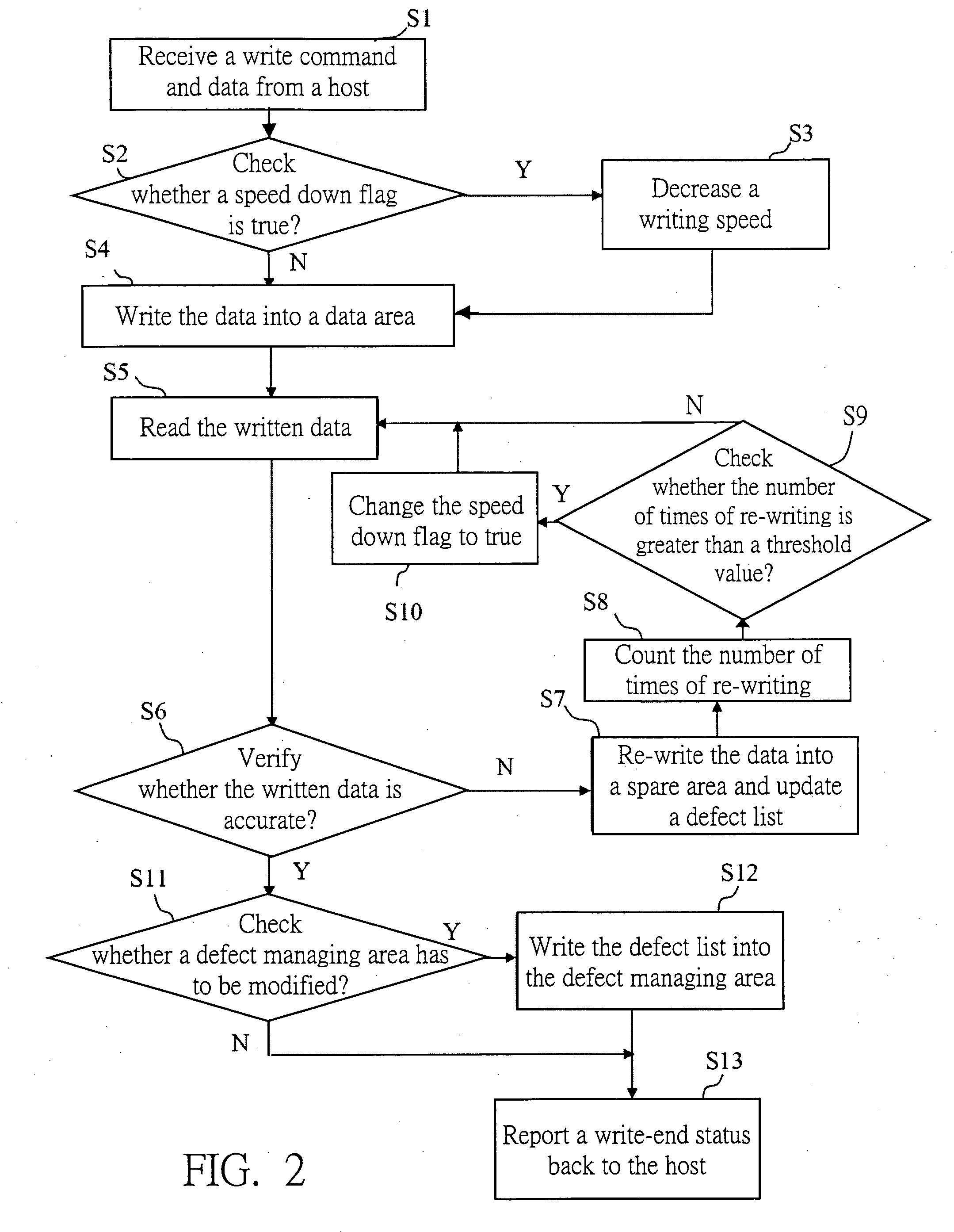
[0008]The invention is directed to a writing method for an optical disk drive, wherein a writing condition of the optical disk drive is adjusted by verifying whether the written data is accurate so that the variations of the optical disk drives can be effectively overcome.
[0009]The invention is also directed to a writing method for an optical disk drive, wherein a writing speed is decreased to enhance the writing quality when the number of times of re-writing data is greater than a predetermined threshold value.
[0010]The invention is further directed to a writing method for an optical disk drive, wherein the condition, in which the writing speed of the optical disk drive has to be decreased, is accurately evaluated to prevent the writing speed from being incorrectly decreased and to keep the overall writing efficiency.

Problems solved by technology

The poor writing quality causes the optical disk drive to spend a longer period of time to correct the error, thereby decreasing the overall efficiency or disabling the written data from being read, and thus influencing the quality of the optical disk drive.
However, the optical disk drive is not adjusted.
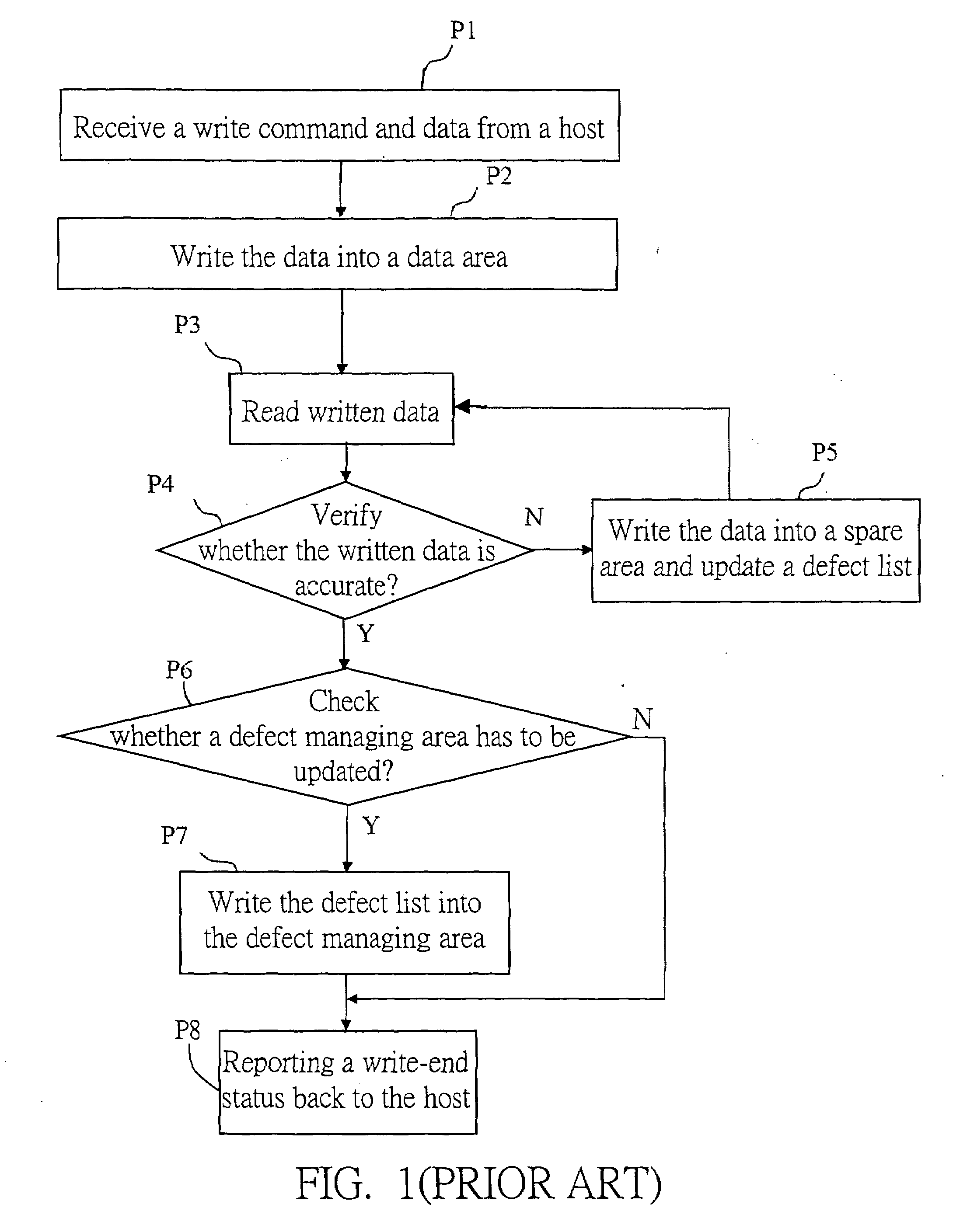
If the optical disk drive has the poor writing quality, many defects are found and the data is re-written into the spare area, the next time of data writing still can generate many defects.
Similarly, the writing quality is poor, and it is time-consuming to improve the defects, which is not advantageous to the overall efficiency of the optical disk drive.
Therefore, the conventional optical disk drive still has some problems to be overcome in the writing method.

Method used


Image

  • Writing method for optical disk drive
  • Writing method for optical disk drive
  • Writing method for optical disk drive

Examples


Embodiment Construction

[0015]The DVD-RAM type optical disk drive actively reads a piece of written data after the piece of written data has been written to verify whether the data has been accurately written. The inaccurately written data is managed as a defect. That is, the accurate data is re-written into a spare area of an optical disk to replace the inaccurate data. The writing method for the optical disk drive according to the invention utilizes the DVD-RAM type optical disk drive to write the data and conduct the defect managing mechanism. When the DVD-RAM type optical disk drive is verifying the writing accuracy, the DVD-RAM type optical disk drive finds that the written data is inaccurate, and thus counts the number of times of re-writing and gives a suitable threshold value of the number of times, such as 8. As long as the number of times of re-writing in the DVD-RAM type optical disk drive exceeds the threshold value, it is judged that the DVD-RAM type optical disk drive may have the poor data w...


PUM


Abstract

A writing method for an optical disk drive includes the following steps. First, a write command and to-be-written data are received from a host. Next, a speed down flag is checked. If the speed down flag is true, a writing speed is decreased; or otherwise the to-be-written data is written into a data area. Next, the written data is read, and accuracy of the written data is verified. If the written data is not accurate, accurate data is re-written into a spare area, and the number of times of re-writing is counted and checked. If the number of times of re-writing is greater than a predetermined threshold value, the speed down flag is changed to true; or otherwise the procedure goes back to the data-writing step to repeat the above-mentioned steps. If the written data is read and verified as accurate, a write-end status is reported back to the host.

Description

[0001]This application claims the benefit of Taiwan application Serial No. 96123224, filed Jun. 26, 2007, the subject matter of which is incorporated herein by reference.BACKGROUND OF THE INVENTION[0002]1. Field of the Invention[0003]The invention relates in general to a writing method for an optical disk drive, and more particularly to a method of speeding down a writing speed of an optical disk drive according to a writing quality.[0004]2. Description of the Related Art[0005]Optical disk drives have properties differing from one another, and tend to generate different writing qualities according to a command of a host and to-be-written data in the same condition. The writing qualities thereof also differ from one another, and the variations thereof are very great. The poor writing quality causes the optical disk drive to spend a longer period of time to correct the error, thereby decreasing the overall efficiency or disabling the written data from being read, and thus influencing ...

Claims


Application Information

Patent Timeline
IPC IPC(8): G11B5/09
CPCG11B7/00458G11B19/041G11B20/1879G11B20/1883G11B2220/2575G11B2020/183G11B2020/1893G11B2220/20G11B2020/1099
Inventor YANG, MILLERHUANG, SHIH-JUNG
Owner QUANTA STORAGE INC
Learn More