Recording material determination apparatus andimage forming apparatus

a technology of material determination and recording material, which is applied in the direction of electrographic process apparatus, thin material processing, instruments, etc., can solve the problems of insufficient determination accuracy in the conventional method, difficult to finely determine the grammage of a recording material, and capture of unfocused image of the surface of the recording material

Inactive Publication Date: 2009-01-01
CANON KK
View PDF4 Cites 39 Cited by
  • Summary
  • Abstract
  • Description
  • Claims
  • Application Information

AI Technical Summary

Benefits of technology

[0017]More particularly, an embodiment of the present invention is directed to a recording material determination apparatus capable of reducing, in a case where the type of a recording material is determined using both a method of determining the type of a recording material by irradiating an ultrasonic wave to

Problems solved by technology

However, particularly, in a case where the grammage of a recording material is determined, the determination accuracy in the conventional method may be insufficient.
However, it

Method used


Image

  • Recording material determination apparatus andimage forming apparatus
  • Recording material determination apparatus andimage forming apparatus
  • Recording material determination apparatus andimage forming apparatus

Examples


first exemplary embodiment

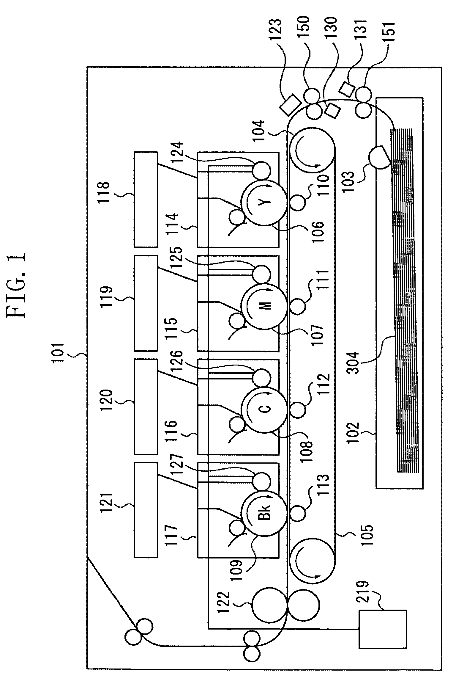
[0068]Next, a recording material determination apparatus according to an exemplary embodiment of the present invention is described below. FIG. 3 illustrates a configuration of a reading sensor for determining a surface condition of a recording material. FIG. 4 illustrates a configuration of an ultrasonic sensor for determining a grammage of a recording material.

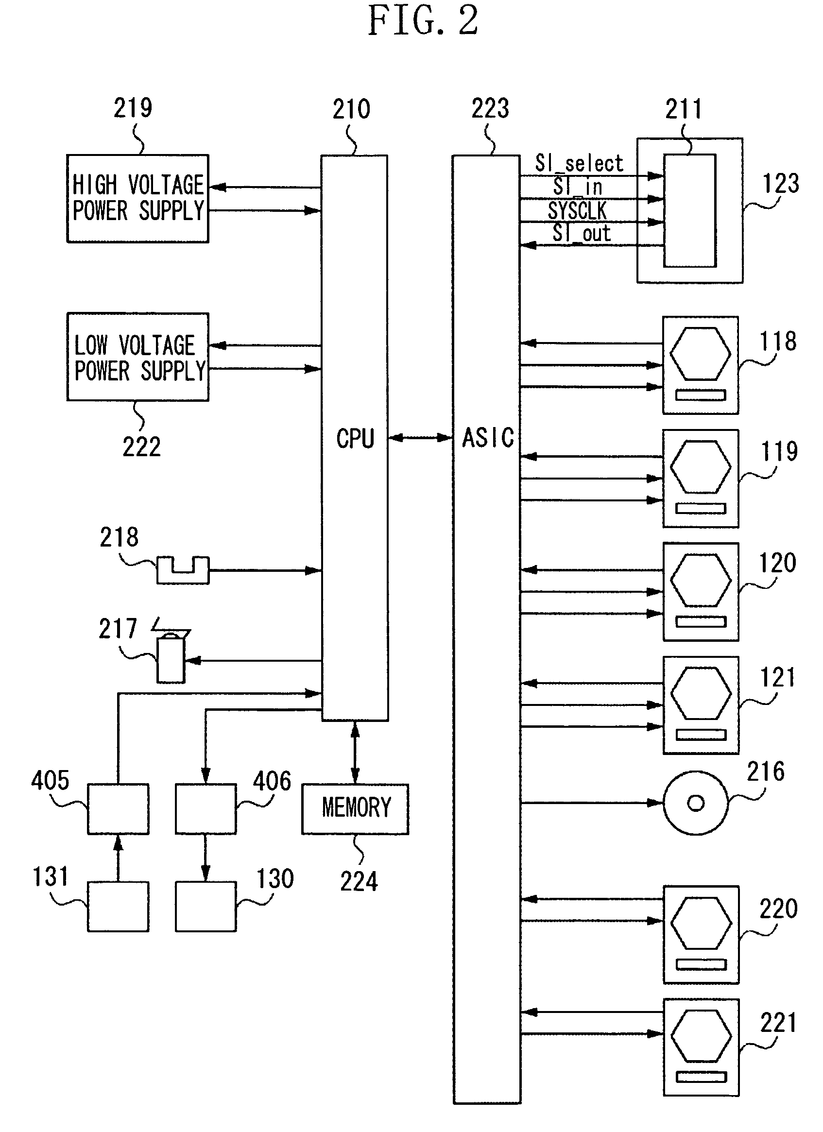
[0069]As illustrated in FIG. 3, the reading sensor 123 for determining the surface condition of a recording material includes a light emitting diode (LED) 301 for irradiating light, a CMOS area sensor 211 for capturing an image, and an imaging lens 303. Incidentally, an image can be captured using a CCD sensor instead of the CMOS area sensor 211.

[0070]Light emitted from the LED 301 serving as a light source is irradiated to a surface of the recording material 304. Reflection light reflected from the recording material 304 is focused via the lens 303 and is formed into an image on the CMOS area sensor 211. Consequently, an im...

second exemplary embodiment

[0130]A configuration of components of a second exemplary embodiment other than the arrangement of the reading sensor 123, the ultrasonic transmitter 130 and the ultrasonic receiver 131, which serve as a ultrasonic sensor, the conveyance roller 150, and the recording material 304 is similar to that of components of the first exemplary embodiment. Therefore, the detailed description of such components of the second exemplary embodiment is omitted.

[0131]In the first exemplary embodiment, the reading sensor 123 is located opposite the ultrasonic sensor across the conveyance roller 150 in the direction of conveying the recording material 304.

[0132]In the second exemplary embodiment, the conveyance roller 150 is configured to include a plurality of conveyance members 150A and 150B provided on a shaft 151, as illustrated in FIG. 14. The reading sensor 123 is located between the conveyance members 150A and 150B. That is, as illustrated in FIG. 14, the reading sensor 123 detects substantial...

third exemplary embodiment

[0139]A configuration of components of a third exemplary embodiment other than the provision of a recording material detection unit therein is similar to those of components of the first and second exemplary embodiments. Therefore, the detailed description of components of the third exemplary embodiment, which are common to the first, second, and third exemplary embodiments, is omitted.

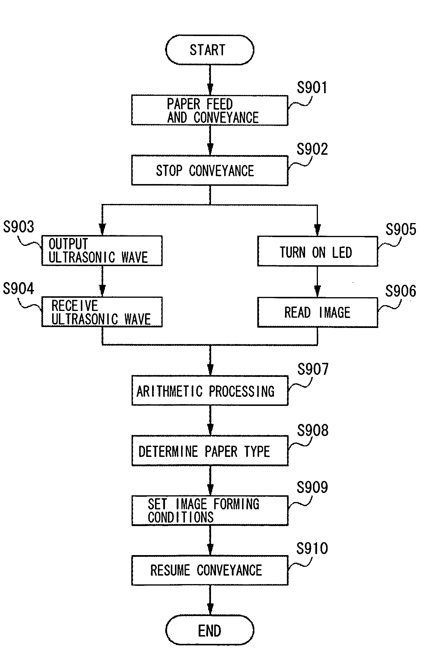
[0140]In the first and second exemplary embodiments, the CPU 210 stops the conveyance of the recording material 304 by stopping the rotation of the conveyance roller 150 at a time at which the recording material 304 is expected to reach the reading sensor 123 and at which a predetermined time period has elapsed since a paper feed timing.

[0141]On the other hand, in the third exemplary embodiment, a recording material detection unit 305 is added to a position at the downstream side of the conveyance roller 150 in the direction of conveying the recording material 304, as illustrated in FIG. 15. For examp...


PUM


Abstract

A recording material determination apparatus includes a first detection unit configured to detect a characteristic corresponding to a surface condition of a recording material based on a captured image of a surface of the recording material, a second detection unit configured to detect a characteristic corresponding to a grammage of the recording material based on an ultrasonic wave detected via the recording material by irradiating the recording material with an ultrasonic wave, and a conveyance unit configured to convey the recording material. The first detection unit and the second detection unit are located opposite each other with respect to the conveyance unit.

Description

BACKGROUND OF THE INVENTION[0001]1. Field of the Invention[0002]The present invention relates to a recording material determination apparatus and to an image forming apparatus to which the recording material determination apparatus is applied. More particularly, the present invention relates to a recording material determination apparatus configured to determine the type of a recording material using a sensor that determines a surface condition of the recording material and a sensor that determines a grammage of the recording material, and to an image forming apparatus to which the recording material determination apparatus is applied.[0003]2. Description of the Related Art[0004]Generally, an image forming apparatus, such as a copying machine or laser printer, forms a toner image on a photosensitive drum, serving as an image carrier, using toner, serving as a developer, and transfers the formed toner image onto a recording material. Then, the image forming apparatus fixes the toner ...

Claims


Application Information

Patent Timeline
IPC IPC(8): G03G15/00
CPCB65H7/02G03G15/5029B65H2515/84B65H2553/30B65H2553/414B65H2557/64B65H2801/06G03G15/65G03G2215/00637G03G2215/00742B65H2511/416B65H2220/03
Inventor KURAMOCHI, YOSHIMIMARUYAMA, SHOJIISHIDA, TSUTOMUEBIHARA, SHUNICHI
Owner CANON KK
Why Eureka
Try Eureka