
Heating device, fixing apparatus, and image forming system

a technology of fixing apparatus and heat dissipation device, which is applied in the direction of mechanical control device, furniture, instruments, etc., can solve the problems of affecting image quality, user dissatisfaction with the mod, and reducing the temperature of the heat dissipation member, so as to improve the effect of background arts technology

Inactive Publication Date: 2009-01-01
RICOH KK
View PDF3 Cites 44 Cited by
  • Summary
  • Abstract
  • Description
  • Claims
  • Application Information

AI Technical Summary

Benefits of technology

[0013]Accordingly, an object of the present invention is to improve su...

Problems solved by technology

However, since a time taken by the start up operation varies depending upon unevenness of parts of the heat-applying source in the temperature priority mode, the user is dissatisfied by the mode
However, the time priory mode can affect an image quality depending on a condition where a fixing apparatus is used.
Specifically, since calorie supplied from a heat source per hour decreases when an input voltage thereto is low, temperature of the heat applying member decreases, so that a fixing error, such as a cold offset, etc., occurs.
Accordingly, it is hard to determine completion of a start up operation for the heat-applying member only based on the elapsing time from the starting up of heat application.

Method used


Image

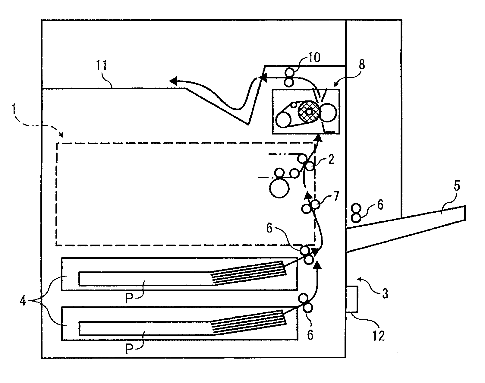
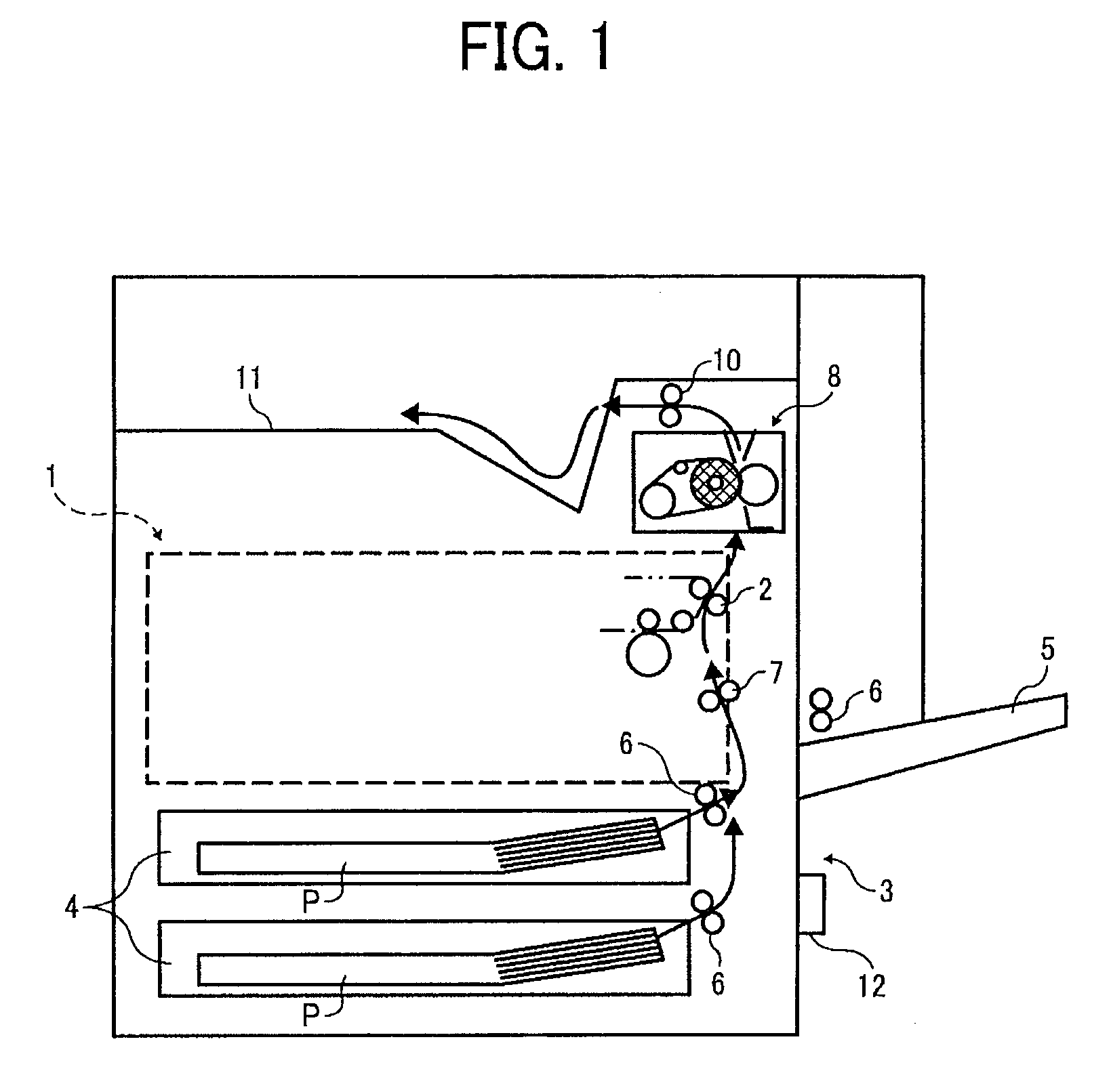
  • Heating device, fixing apparatus, and image forming system
  • Heating device, fixing apparatus, and image forming system
  • Heating device, fixing apparatus, and image forming system

Examples


second embodiment

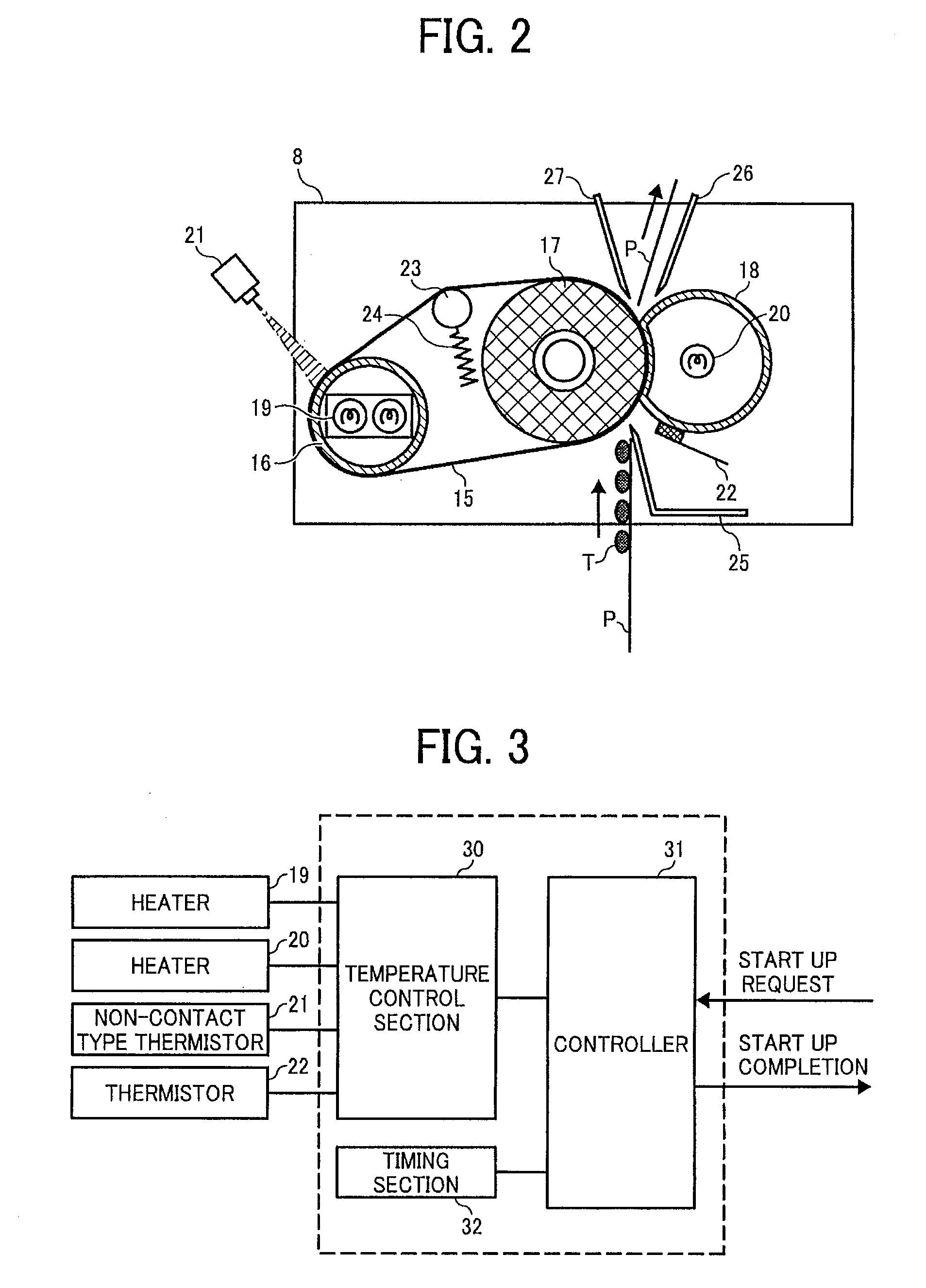
[0070]An exemplary sequence of a heat application start up operation executed in the fixing section is described with reference to FIG. 10. The temperature / humidity sensor 12 detects ambient temperature in steps S2-3, and a start up operation completion temperature Tftemp and a heat application start up operation completion time Tftime are determined in accordance with the detection result with reference to the data table of FIG. 9 in step S2-4. The other steps S2-1, S2-2, and S2-5 to S2-11 are the same as those S1-1, S1-2, and S1-3 to S1-9 of FIG. 4.

[0071]Now, an exemplary control section of a third embodiment of a fixing apparatus is described with reference to FIG. 11. This control section is substantially the same as the control section of the second embodiment of FIG. 8, and executes controlling also based on detection info transmitted from a power meter 34 that detects power supplied to an apparatus. Specifically, the power supplied to the apparatus is detected and one of the ...

third embodiment

[0072]An exemplary sequence of a heat application start up operation executed in the fixing section is described with reference to FIG. 12. The power meter 34 detects power supplied in steps S3-3, and a start up operation completion temperature Tftemp and a heat application start up operation completion time Tftime are determined by matching the power detection result with data to which correspondence is previously set correspondence thereto in step S3-4. The other steps S3-1, S3-2, and S3-5 to S3-11 are the same as those S1-1, S1-2, and S1-3 to S1-9 of FIG. 4.

[0073]When the power is large, temperature of the fixing belt 15 quickly increases because calorie of heater 19 of the heat source becomes large. Further, since drop of temperature of the fixing belt 15 becomes small when a sheet is fed after completion of the heat application start up operation, the start up operation completion temperature can be lowered.

[0074]An exemplary sequence of a heat application start up operation ex...


PUM

PropertyMeasurementUnit
Temperatureaaaaaaaaaa
Timeaaaaaaaaaa
Pressureaaaaaaaaaa

Abstract

A heating device includes a heat applying member heated by a heat source, a pressure applying member pressure contacting the heat applying member with a prescribed pressure, and a temperature detection device that detects temperature of the heat applying member. A timing device is provided to count time elapsing from when the heat source starts heating the heat-applying member. A control device is provided to determine that heat application as a start up operation to the heating member is completed when the temperature detected by the temperature detection device reaches a prescribed threshold and the elapsing time counted by the timing device reaches a prescribed threshold.

Description

CROSS REFERENCE TO RELATED APPLICATION[0001]This application claims priority under 35 USC § 119 to Japanese Patent Application No. 2007-168707, filed on Jun. 27, 2007, the entire contents of which are herein incorporated by reference.BACKGROUND OF THE INVENTION[0002]1. Field of the Invention[0003]This invention relates to a heating device including a heat applying member heated by a heat source and a pressure applying member pressure contacting the heat member with a prescribed pressure for fixing a toner image onto a printing sheet by means of heat and pressure, a fixing apparatus including the heating device, and an image forming system, such as a copier, a printer, a facsimile, etc., including the fixing apparatus.[0004]2. Discussion of the Background Art;[0005]A conventional fixing apparatus mounted on an image forming system performs fixing by applying heat and pressure to a printing medium fed between a heat applying member and a pressure applying member while pressurizing mel...

Claims


Application Information

Patent Timeline
IPC IPC(8): G03G15/20F27D19/00B32B37/06
CPCG03G15/2039G03G2215/2032
Inventor FUJIMOTO, IPPEI
Owner RICOH KK
Learn More