Bus bar system, method, and kit

a bus bar and bus system technology, applied in the direction of coupling device connection, coupling protective earth/shielding arrangement, electrical equipment, etc., can solve the problems of increasing the theft of grounding bus bars, increasing the cost of copper, and affecting the use of copper, so as to reduce the use of copper and the effect of less mass per attachment lug

Inactive Publication Date: 2009-01-01
DULEY WAYNE C
View PDF7 Cites 15 Cited by
  • Summary
  • Abstract
  • Description
  • Claims
  • Application Information

AI Technical Summary

Benefits of technology

[0006]The present invention relates to a component within an electrical system, including systems for harnessing and dispersing current or voltage surges. The present invention is a replacement bus system having one or more conductive shafts supporting attachment lugs and one or more spacers that ride along the conductive shaft; the spacers are conductive and separate the attachment lugs. The lugs and spacers may be secured onto the shaft by a locking mechanism. By providing a shaft on which the lugs may ride, the wires are configured transversely to conventional approaches, enabling a greater number of wires to be connected over a given length. This configuration also enables the structure to be manufactured from stainless steel, except for the spacers, which may be manufactured from tinned copper. Because the spacers represent less mass per attachment lug than is used in a conventional bus bar, the present invention produces a significant reduction in copper use. Moreover, experimental data show that the present invention performs equivalently to a copper bus bar.

Problems solved by technology

However, copper is a relatively expensive material, particularly for the robust systems capable of grounding lightning strikes.
The value of copper has contributed to an increase in theft of grounding bus bars.
In the grounding of often remote towers for cellular telephones, this problem is particularly acute.

Method used


Image

  • Bus bar system, method, and kit
  • Bus bar system, method, and kit
  • Bus bar system, method, and kit

Examples


Embodiment Construction

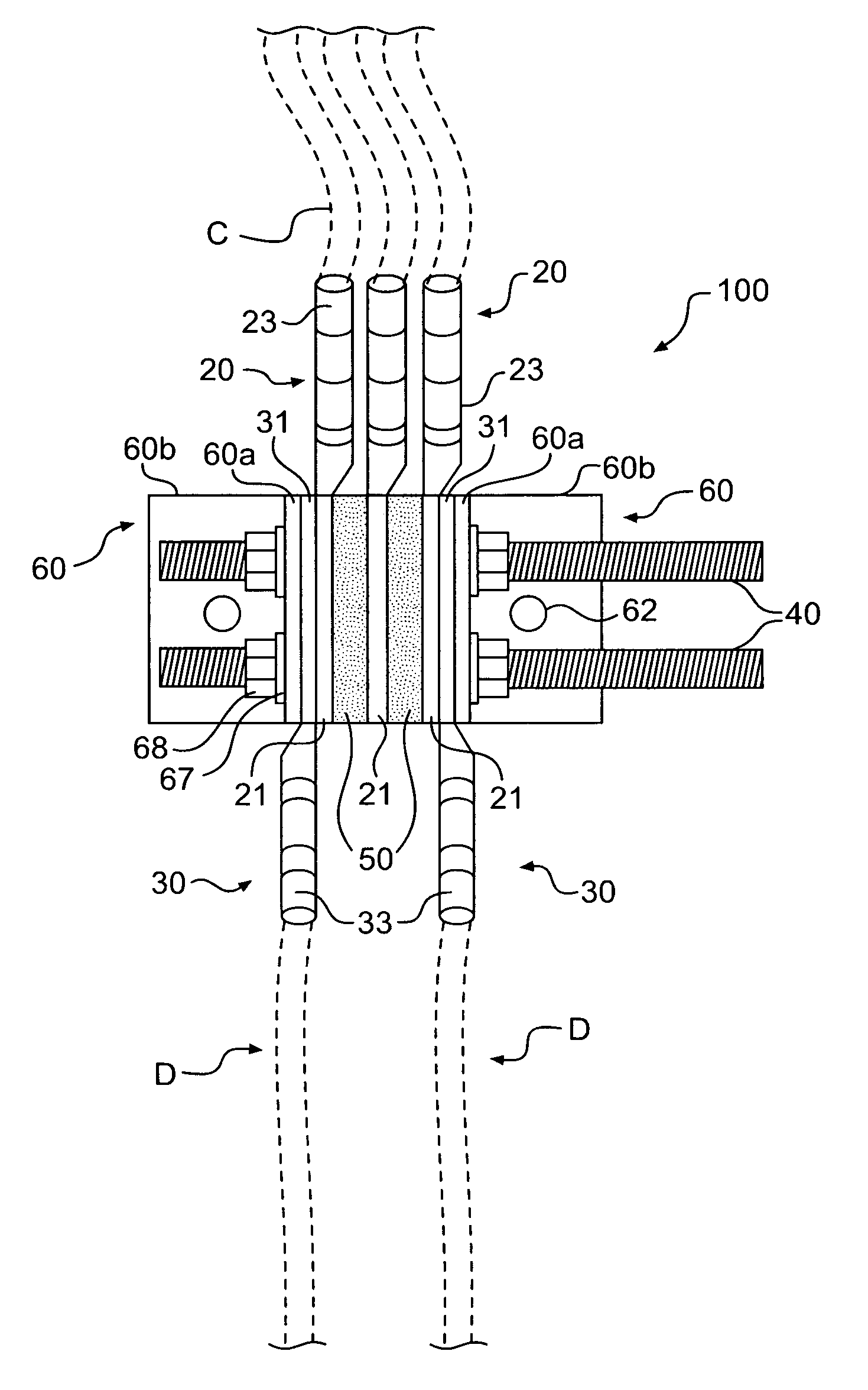
[0027]The present invention is a replacement bus system having one or more shafts supporting attachment lugs and one or more spacers that ride along the conductive shaft; the spacers are conductive and separate the attachment lugs. Although the present invention is not limited to grounding systems, for convenience of description it will be described in the context of a grounding system.

[0028]Wire lugs are terminal conductive electrical connectors; the lugs have a barrel end and a tang end. A terminal section of wire may be stripped to expose the conductor, which can then be crimped within the barrel of the lug, affixing the lug to the wire. The lug tang end includes a flat portion defining one or more bolt stud holes within it.

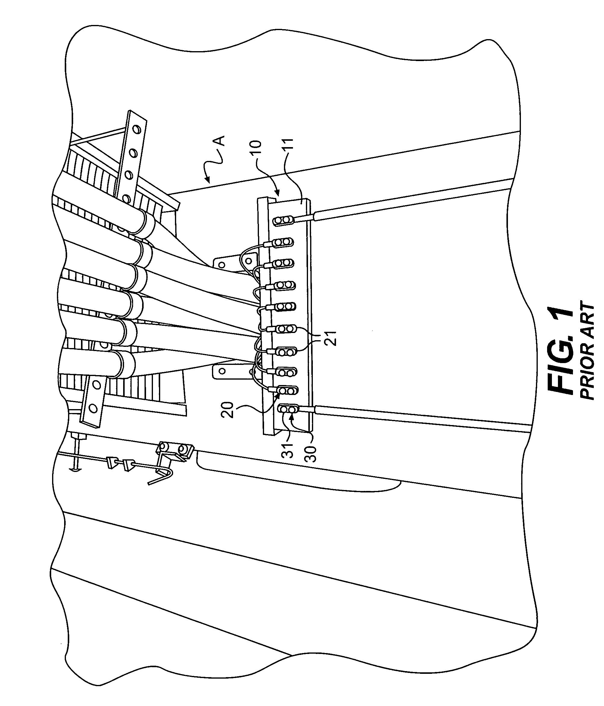
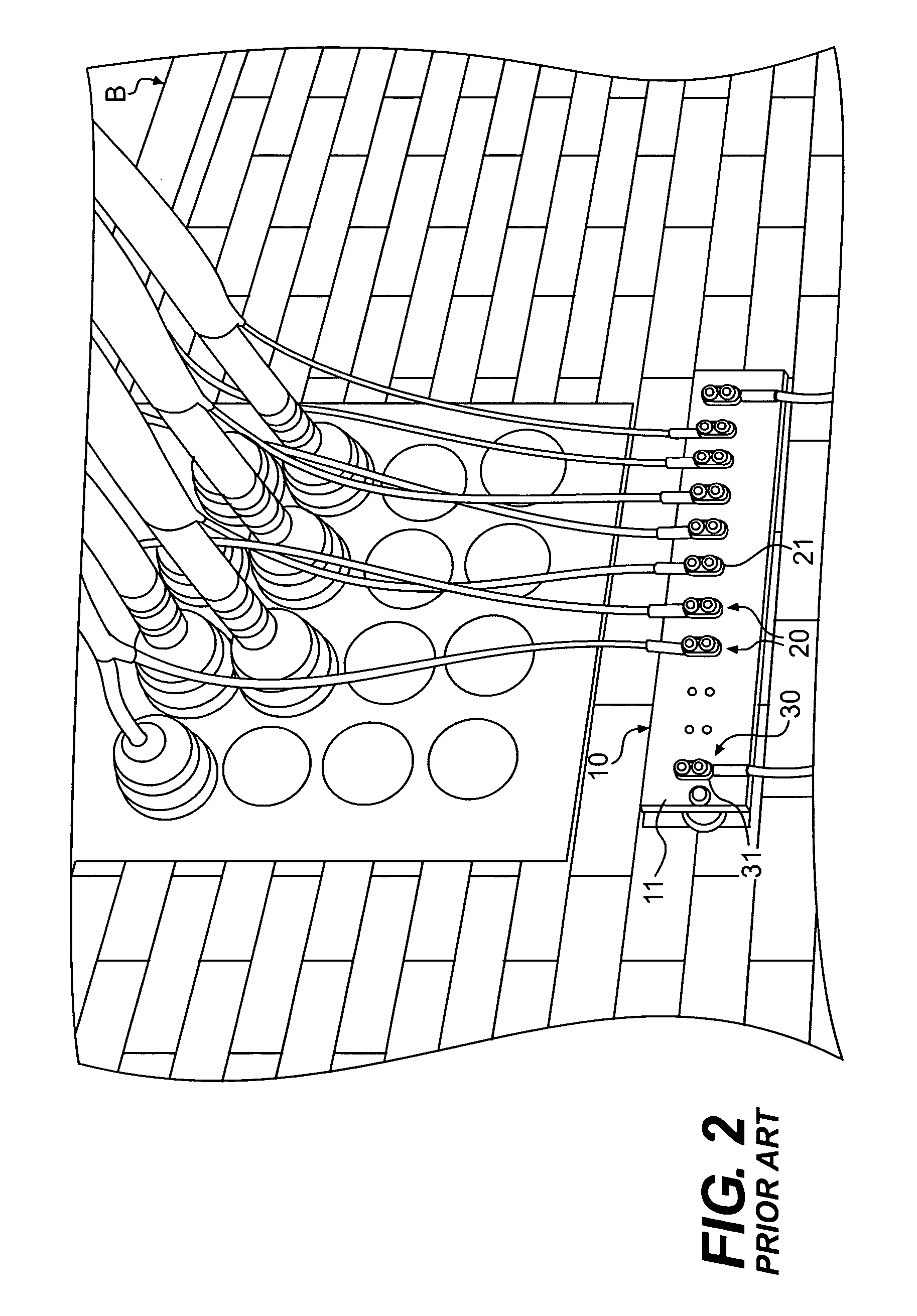
[0029]Such lugs are commonly used in electrical power or grounding applications. Conventional bus bars 10, as shown affixed to cellular telephone tower A in FIG. 1 and to building B in FIG. 2, support the lugs 20 and 30 in an orientation in which the lug tang ...


PUM


Abstract

A replacement bus system having one or more conductive shafts supporting wire attachment lugs and spacers that ride along the conductive shaft; the spacers are conductive and separate the attachment lugs. The lugs and spacers may be secured onto the shaft by a locking mechanism. By providing a shaft on which the lugs may ride, the wires are configured transversely to conventional approaches, enabling a greater number of wires to be connected over a given length and a wider variety of relative orientation of wires. This configuration also enables much of the structure to be manufactured from stainless steel or other non cuprous metal, except for the spacers, which may be manufactured from tinned copper.

Description

CROSS-REFERENCE TO PROVISIONAL APPLICATION[0001]This application claims the benefit of U.S. Application Ser. No. 60 / 937,352, filed Jun. 27, 2007, entitled Bus Bar System and naming Wayne C. Duley as the inventor, the disclosure of which is hereby incorporated herein by reference in its entirety as if set forth fully herein.FIELD OF INVENTION[0002]This invention relates generally to a component for use in electrical systems, including grounding and energy dispersion systems directed to protect items from damaging current and voltage surges.BACKGROUND OF THE INVENTION[0003]Grounding and energy dispersion systems have been used historically to prevent current and voltage surges from damaging sites, structures, and electrical equipment. Conventional grounding systems may include elements such as ground rods, ground plates, ground electrodes, enhanced ground rods and chemical rods.[0004]Grounding systems, like certain other electrical systems, often involve the collection of several wire...

Claims


Application Information

Patent Timeline
Patent Type & Authority Applications(United States)
IPC IPC(8): H01R11/01
CPCH01R11/12H01R11/01
Inventor DULEY, WAYNE C.
Owner DULEY WAYNE C
Why Eureka
Try Eureka