Process for making shock absorber fluid

a technology of shock absorber and fluid, which is applied in the direction of hydrocarbon oil treatment, lubricant composition, base materials, etc., can solve the problems of shock absorber paint on the shock absorber, and the failure of current oils

Active Publication Date: 2009-01-01
CHEVROU USA INC
View PDF13 Cites 21 Cited by
  • Summary
  • Abstract
  • Description
  • Claims
  • Application Information

AI Technical Summary

Benefits of technology

[0007]b. blending the base oil fraction with less than 4.0 wt % combined viscosity index improver and pour point depressant, based on the total shock absorber fluid, to produce the shock absorber fluid having an air release after 1 minute by DIN 51381 of less than 0.8 vol. %.

Problems solved by technology

Current oils often fail due to high temperature and may even get so hot that they melt the paint on the shock absorbers.

Method used


Image

  • Process for making shock absorber fluid
  • Process for making shock absorber fluid
  • Process for making shock absorber fluid

Examples


example 1

[0140]Two base oils were prepared by hydroisomerization dewaxing a Co-based Fischer-Tropsch wax and a Fe-based. Fischer-Tropsch wax over a Pt / SAPO-11 catalyst at 1000 psi, 0.5-1.5 LHSV, and between 660-690° C. They were subsequently hydrotreated to reduce the level of aromatics and olefins, then vacuum distilled into fractions.

[0141]The FIMS analysis was conducted on a Micromass Time-of-Flight spectrophotometer. The emitter on the Micromass Time-of-Flight was a Carbotec 5 um emitter designed for FI operation. A constant flow of pentaflourochlorobenzene, used as lock mass, was delivered into the mass spectrometer via a thin capillary tube. The probe was heated from about 50° C. up to 600° C. at a rate of 100° C. per minute. Test data on the two Fischer-Tropsch derived lubricant base oils are shown in Table II, below.

TABLE IISample PropertiesFT-XXL-1FT-XL-1Made from:Co-based Fischer-Fe-based Fischer-Tropsch waxTropsch waxViscosity at 100° C., mm2 / s2.182.981Viscosity Index123127Pour Po...

example 2

[0142]Three different blends of shock absorber fluid were prepared using the FT-XXL-1 and FT-XL-1 base oils of example 1. The formulations and properties of these blends are summarized in Table III.

TABLE IIISAFABlend of FT-Component, Wt %XXL-1 andSAFBSAFCBase OilsFT-XL-1FT-XL-1FT-XL-1Wt % Base Oil96.1596.1597.05Wt % Viscosity Index Improver0.90.90.0Wt % DI Additive Package2.552.552.55Wt % Pour Point Depressant0.40.40.4Wt % VII and PPD1.11.10.4Total100.00100.00100.00

[0143]Note that SAFA, SAFB, and SAFC all have less than 4 wt % combined viscosity index improver and pour point depressant, with SAFC only having 0.4 wt %.

[0144]The properties of these three different shock absorber fluids are shown in Table IV

TABLE IVPropertiesSpec.SAFASAFBSAFCViscosity at 100° C., mm2 / s2.563.233.11Viscosity Index153157135Aniline Point, ° C.>88110.2111.3112.1Brookfield Vis @ −18° C.,100190160MPa · sBrookfieid Vis @ −30° C.,270500510MPa · s

[0145]All three of these oils showed exceptional viscometric prope...

example 3

[0146]Two Fischer-Tropsch derived base oils were made from hydrotreated Co-based Fischer-Tropsch wax. The properties of these two base oils are summarized in Table V.

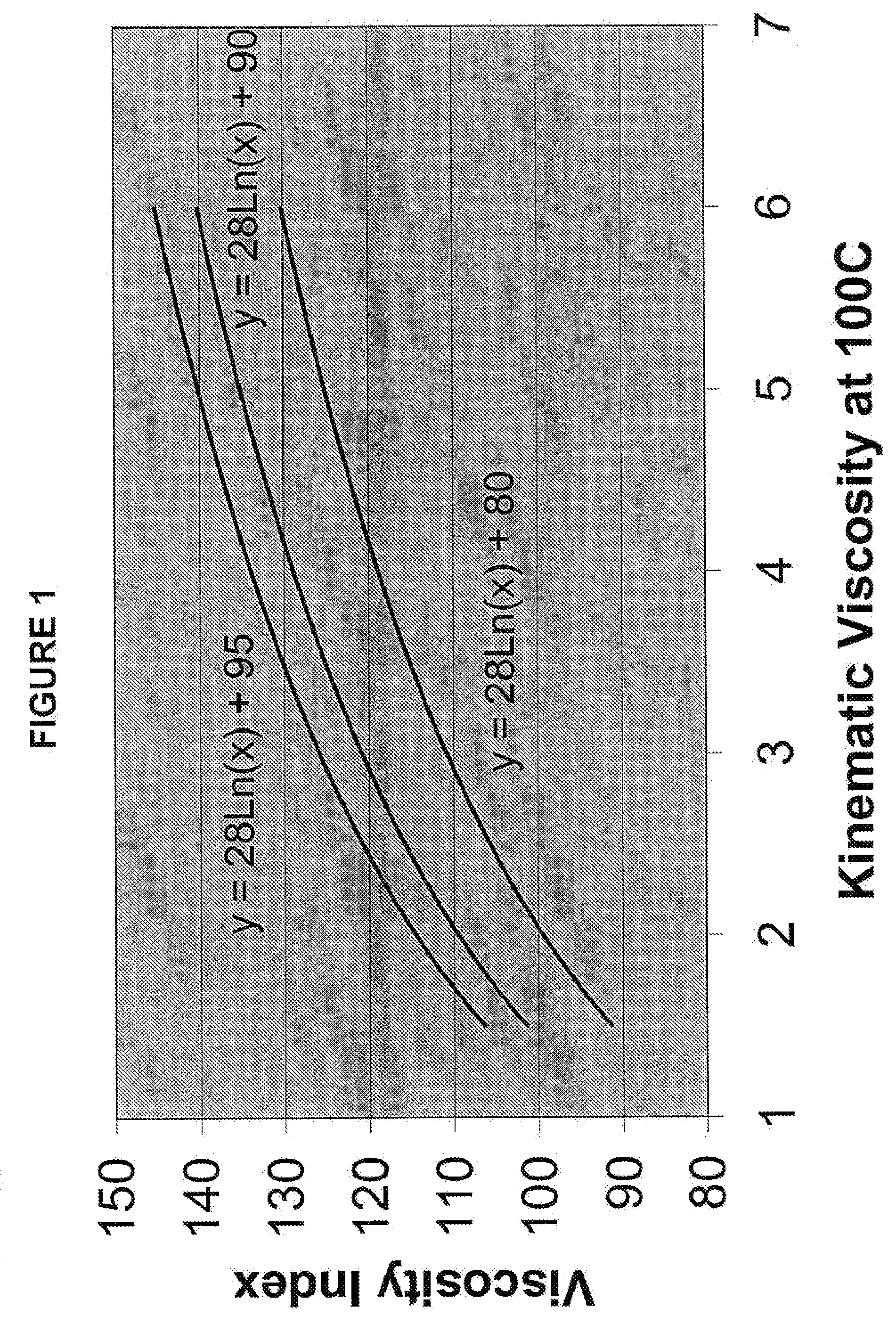
TABLE VSample PropertiesFT-XXL-2FT-XL-2Viscosity at 100° C., mm2 / s2.3623.081Viscosity Index123124Pour Point, ° C.−39−43Wt % Aromatics0.02050.0043Wt % OlefinsFIMS, Wt %Alkanes75.372.51-Unsaturations20.723.12- to 6- Unsaturations4.04.4Total100.0100.0Total Molecules with24.727.5Cycloparaffinic FunctionalityRatio of Monocycloparaffins to5.25.3MulticycloparaffinsX in the equation: VI = 28 ×98.992.5Ln(VIS100) + XTGA Noack Volatility, wt %63.13.1.1Noack Volatility Factor65.536.76% Naphthenic Carbon by n-d-M3.864.83Average Molecular Weight329381


PUM

PropertyMeasurementUnit
Brookfield viscosityaaaaaaaaaa
viscosity indexaaaaaaaaaa
kinematic viscosityaaaaaaaaaa

Abstract

A process to make a shock absorber fluid having improved performance properties, the properties including an air release after 1 minute by DIN 51381 of less than 0.8 vol %, a kinematic viscosity at 100° C. less than 5 mm2/s and an aniline point greater than or equal to 95° C., or meeting the specifications for Kayaba 0304-050-0002 or VW TL 731 class A. The shock absorber fluid is made by blending a base oil having less than 10 wt % naphthenic carbon and a high viscosity index with low levels of (or no) viscosity index improver and pour point depressant.

Description

RELATED APPLICATIONS[0001]This application is related to two other applications filed concurrently with this application. Those applications are “Functional Fluid Compositions” (by Mark Sztenderowicz, John Rosenbaum, Marc De Weerdt, Thomas Plaetinck, Chantal Swartele, and Stephen Miller), and “Power Steering Fluid” (by John Rosenbaum, Marc De Weerdt, and Kurt Schuermans).FIELD OF THE INVENTION[0002]This invention is directed to processes to make shock absorber fluids having improved performance properties.BACKGROUND OF THE INVENTION[0003]Functional fluids are lubricants used in enclosed systems to transmit power. Examples of systems where functional fluids are used include shock absorbers, hydraulic systems, power steering systems, and transmissions. Shock absorber fluids are low viscosity oils that must operate at a wide temperature range, especially high temperature. Current oils often fail due to high temperature and may even get so hot that they melt the paint on the shock absor...

Claims


Application Information

Patent Timeline
Patent Type & Authority Applications(United States)
IPC IPC(8): C10M105/64C10M105/00
CPCC10N2230/08C10N2230/68C10M2209/084C10N2240/08C10M2205/173C10M2205/026C10N2230/18C10N2230/02C10N2270/00C10N2220/022C10M2205/028C10M2205/04C10N2220/021C10N2230/00C10M169/04C10M177/00C10M2205/022C10N2020/02C10N2020/04C10N2030/00C10N2030/02C10N2030/08C10N2030/18C10N2040/08C10N2070/00C10N2030/68C10M171/00
Inventor SWARTELE, CHANTAL R.ROSENBAUM, JOHN M.DE WEERDT, MARC J.PLAETINCK, THOMASMILLER, STEPHEN J.SZTENDEROWICZ, MARK L.
Owner CHEVROU USA INC
Why Eureka
Try Eureka