
Structural terminus implemented to inhibit explosive effect

a technology of structural terminus and blockage effect, applied in the direction of war-like protection, building components, building types, etc., can solve the problem that panel elements are also not implemented

Inactive Publication Date: 2009-01-08
SALZER SICHERHEITSTECHN
View PDF13 Cites 4 Cited by
  • Summary
  • Abstract
  • Description
  • Claims
  • Application Information

AI Technical Summary

Benefits of technology

[0009]Accordingly, in another aspect of the invention, a significantly more stable attachment of the reinforcement profile, which typically comprises steel, to the structure part is possible than is the case with the frame elements, which typically comprise light metal or plastic. The additional connection of the butt connector to the reinforcement profile and / or to the coupling element is also distinguished by high rigidity and high stability.
[0010]To achieve a connection between the reinforcement profile and the coupling element having a simple construction, according to one embodiment of the invention, the reinforcement profile has free end sections extending beyond the front sides of the first frame element on both ends.
[0014]According to an advantageous refinement of the invention, the reinforcement profiles are provided on both ends with a welded closure plate, in which at least one threaded hole is located, into which a screw penetrating the coupling element is screwed. On one hand a stable type of the connection is thus produced and on the other hand the mounting of the structural terminus is simplified.
[0016]Furthermore, it is advantageous if the stop leg is formed by a L-profile, the L-profile and the plate being connected to the reinforcement profile using a shared screw.

Problems solved by technology

In many cases, the panel elements are also not implemented in such a manner that they may withstand a pressure strain caused by an explosion.

Method used


Image

  • Structural terminus implemented to inhibit explosive effect
  • Structural terminus implemented to inhibit explosive effect
  • Structural terminus implemented to inhibit explosive effect

Examples


Embodiment Construction

[0033]Throughout all the Figures, same or corresponding elements are generally indicated by same reference numerals. These depicted embodiments are to be understood as illustrative of the invention and not as limiting in any way. It should also be understood that the drawings are not necessarily to scale and that the embodiments are sometimes illustrated by graphic symbols, phantom lines, diagrammatic representations and fragmentary views. In certain instances, details which are not necessary for an understanding of the present invention or which render other details difficult to perceive may have been omitted.

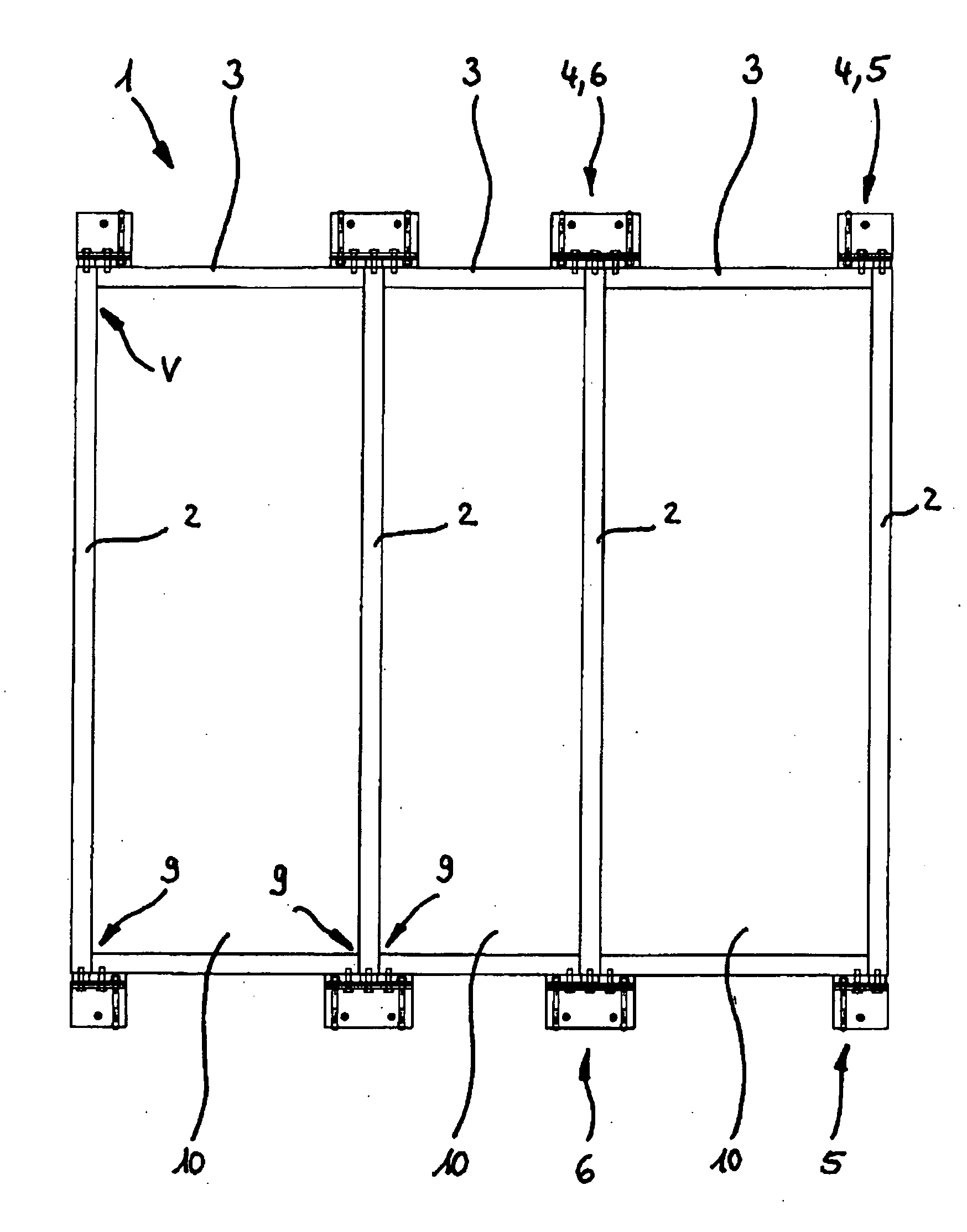
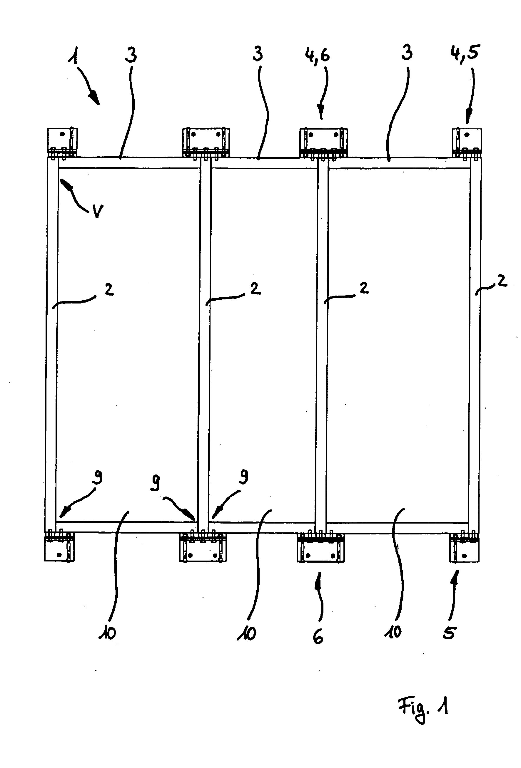
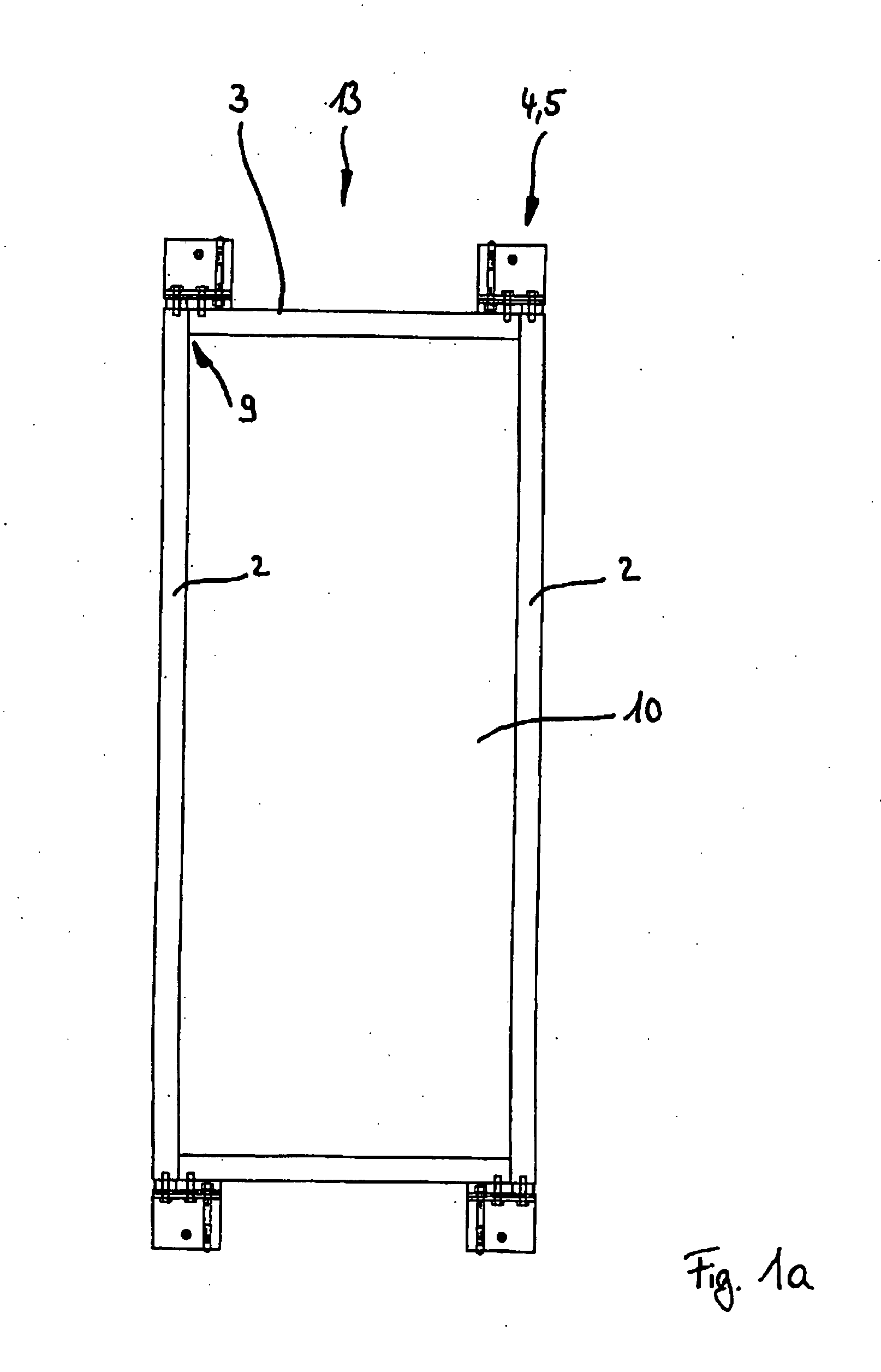
[0034]Turning now to the drawing, and in particular to FIG. 1, there is shown a structural terminus 1, which is implemented as a post-and-beam façade to inhibit explosive effect. The structural terminus 1 has four posts running in the vertical direction as the first frame elements 2 and two beams running in the horizontal direction as the second frame elements 3, each made of ...


PUM


Abstract

The invention relates to a structural terminus for inhibiting explosive effect which includes a flat panel element delimited on one hand by two first hollow profiles frame elements running parallel to one another and whose anchoring ends are anchored on a structure part opposite to one another in relation to a structure opening to be closed using an assigned coupling element and which each extend continuously between anchoring points, and on the other hand by two second hollow profile frame elements running transversely to the first frame elements such that the second frame elements being placed between anchoring ends and butt connectors inserted in the butt ends being connected to an external lateral face of the first frame element, each of the first frame elements has a continuous reinforcement profile connected to the assigned coupling element in their interior, and the butt connectors are connected to the reinforcement profile and / or to the coupling elements.

Description

CROSS REFERENCE TO RELATED APPLICATIONS[0001]This application claims the benefit of priority under 35 U.S.C §119 of German Utility Model 20 2007 005 640.0 filed on Apr. 17, 2007 and of German Utility Model 20 2007 004 060.1 filed on Mar. 15, 2007, the disclosures of which are incorporated hereby by reference.BACKGROUND OF THE INVENTION[0002]The invention relates to a structural terminus and in particular to a structural terminus implemented to inhibit explosive effects.[0003]In the meaning of the present application, a structural terminus is a planar terminus element, which is implemented as openable or permanently closed and may be provided with a transparent or opaque panel. Structural termini of this type are generally known as so-called post-and-beam façades, whose vertical frame elements (“posts”) and horizontal frame elements (“beams”) form fields, in which and / or in front of which the panel elements are situated. Post-and-beam façades may be constructed in such a manner that ...

Claims


Application Information

Patent Timeline
IPC IPC(8): E04B2/06
CPCE04B2/96E06B5/12E04H9/04
Inventor SALZER, HEINRICH
Owner SALZER SICHERHEITSTECHN
Learn More