
Crane control, crane and method
a crane and control technology, applied in the direction of cranes, load-engaging elements, safety gear, etc., can solve the problems of not being taken, not being provided nor possible in the known crane control, and the sensor arrangement and control of the crane known, so as to improve the damping of the spherical pendular oscillation. , the effect of easy and safer alignment of the cran
- Summary
- Abstract
- Description
- Claims
- Application Information
AI Technical Summary
Benefits of technology
Problems solved by technology
Method used
Image

Examples
Embodiment Construction
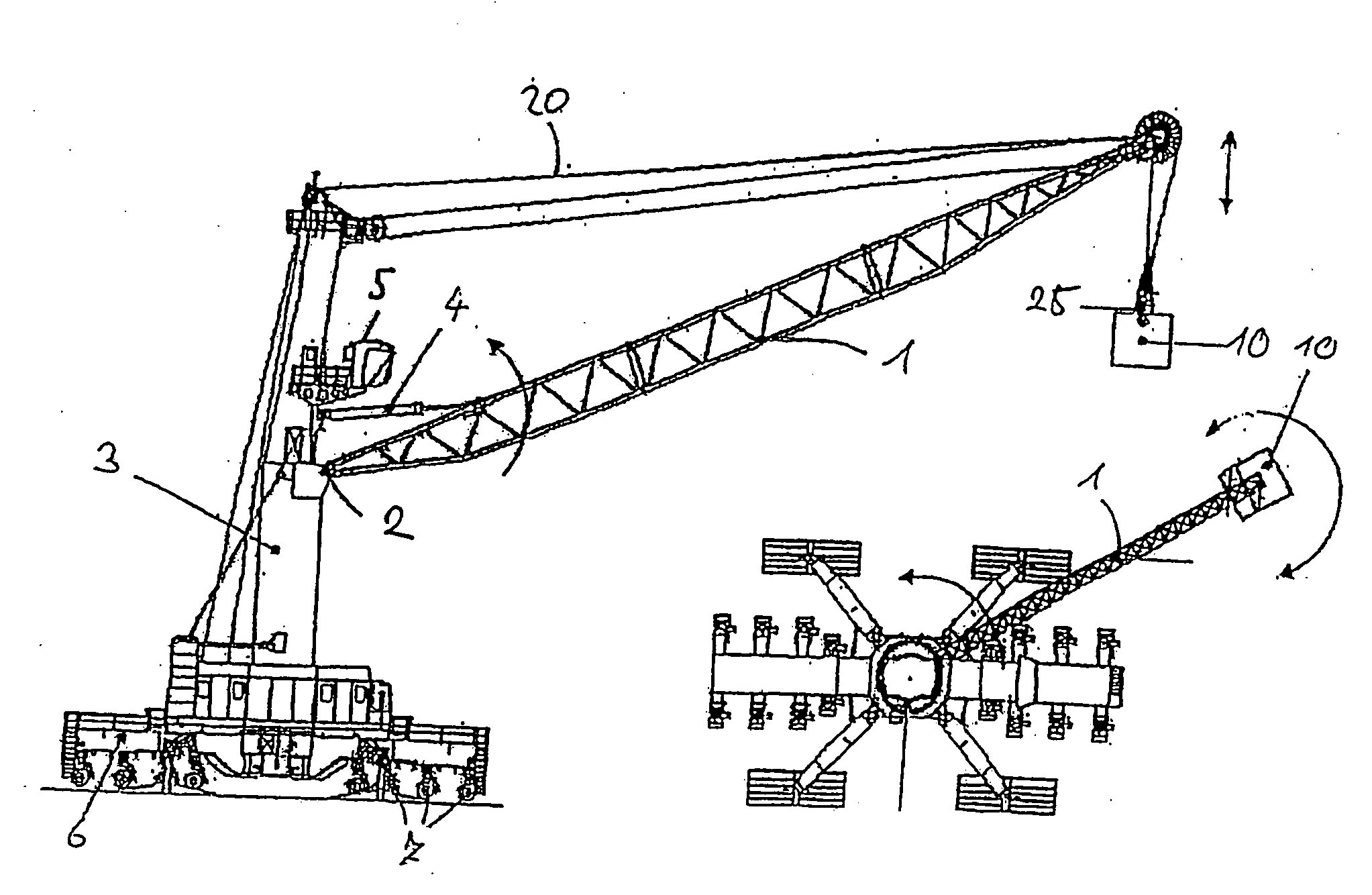
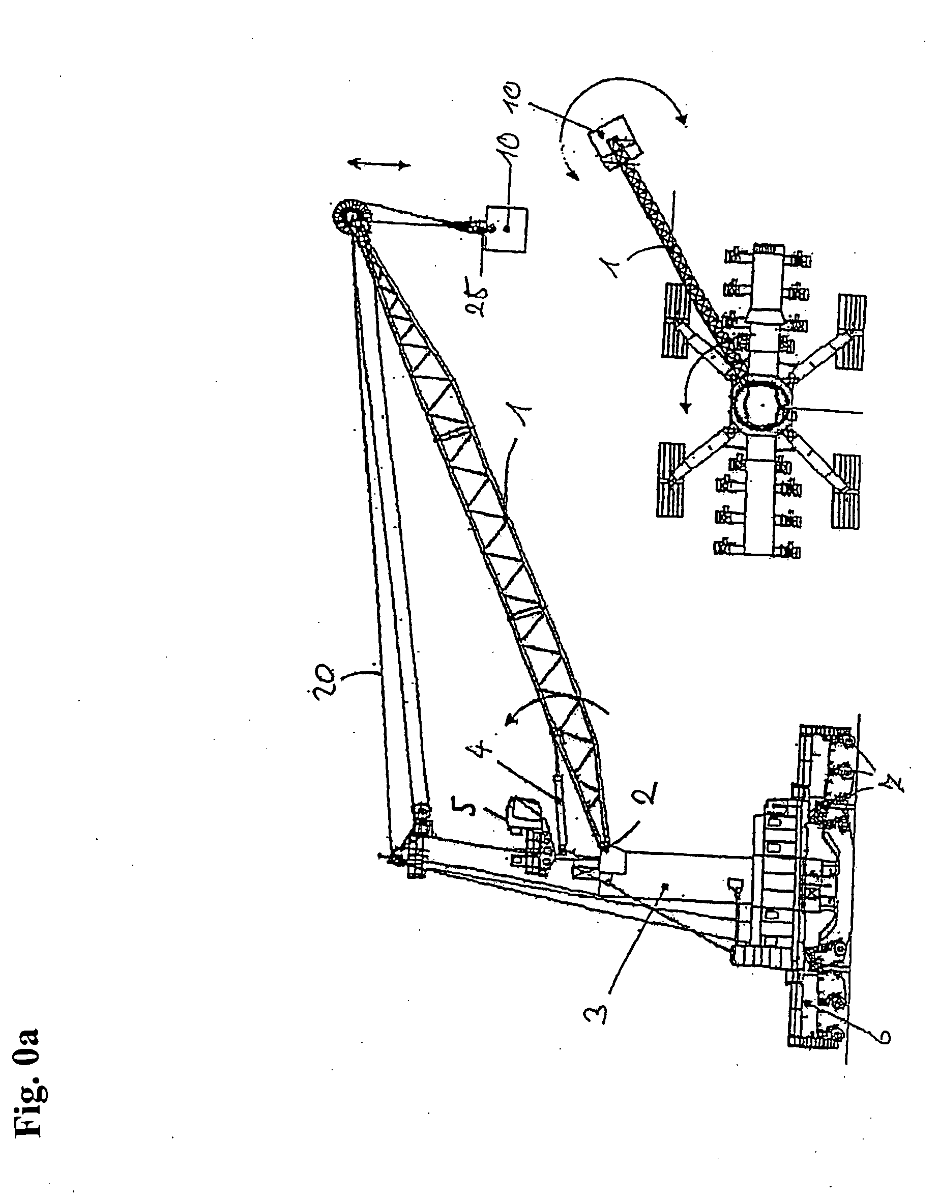
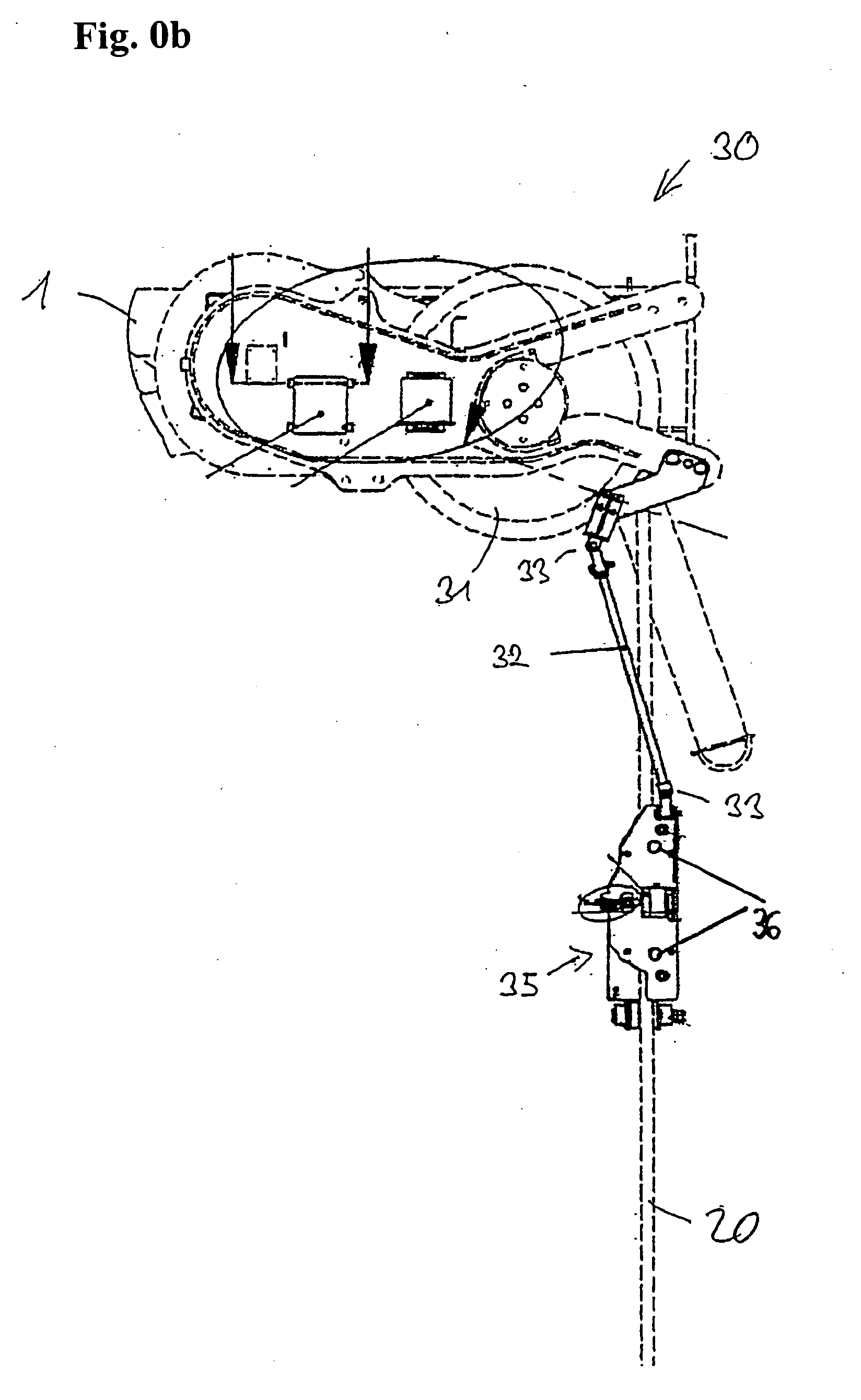
[0099]FIG. 0a shows an embodiment of a boom crane in accordance with the invention, here of a mobile harbour crane, as they are frequently used for performing freight handling operations in harbours. Such boom cranes can have load capacities of up to 140 t and a cable length of up to 80 m. The embodiment of the crane in accordance with the invention comprises a boom 1, which can be swivelled up and down about a horizontal axis 2 with which it is hinged to the tower 3. The tower 3 can in turn be slewed about a vertical axis, whereby the boom 1 is also slewed. For this purpose, the tower 3 is rotatably mounted on an undercarriage 6, which can be moved by wheels 7. For slewing the tower 3, non-illustrated positioners are provided, and for luffing up the boom 1 the actuator 4. The cable 20 for lifting the load 10 is guided over a deflection pulley at the boom head, with the length of the cable 20 being adjustable by winches. On a load suspension point 25, a load suspension device is arr...
PUM
 Abstract
Description
Claims
Application Information