Welder with intelligent battery charger

a battery charger and welding unit technology, applied in the field of portable welding systems, can solve the problems of lack of intelligence in welding units to supply power correctly and safely to other applications

Active Publication Date: 2009-01-08
ILLINOIS TOOL WORKS INC
View PDF9 Cites 27 Cited by
  • Summary
  • Abstract
  • Description
  • Claims
  • Application Information

AI Technical Summary

Problems solved by technology

In addition, welding units lack the intelligence to supply power correctly and safely to other applications, such as batteries.

Method used


Image

  • Welder with intelligent battery charger
  • Welder with intelligent battery charger
  • Welder with intelligent battery charger

Examples


Embodiment Construction

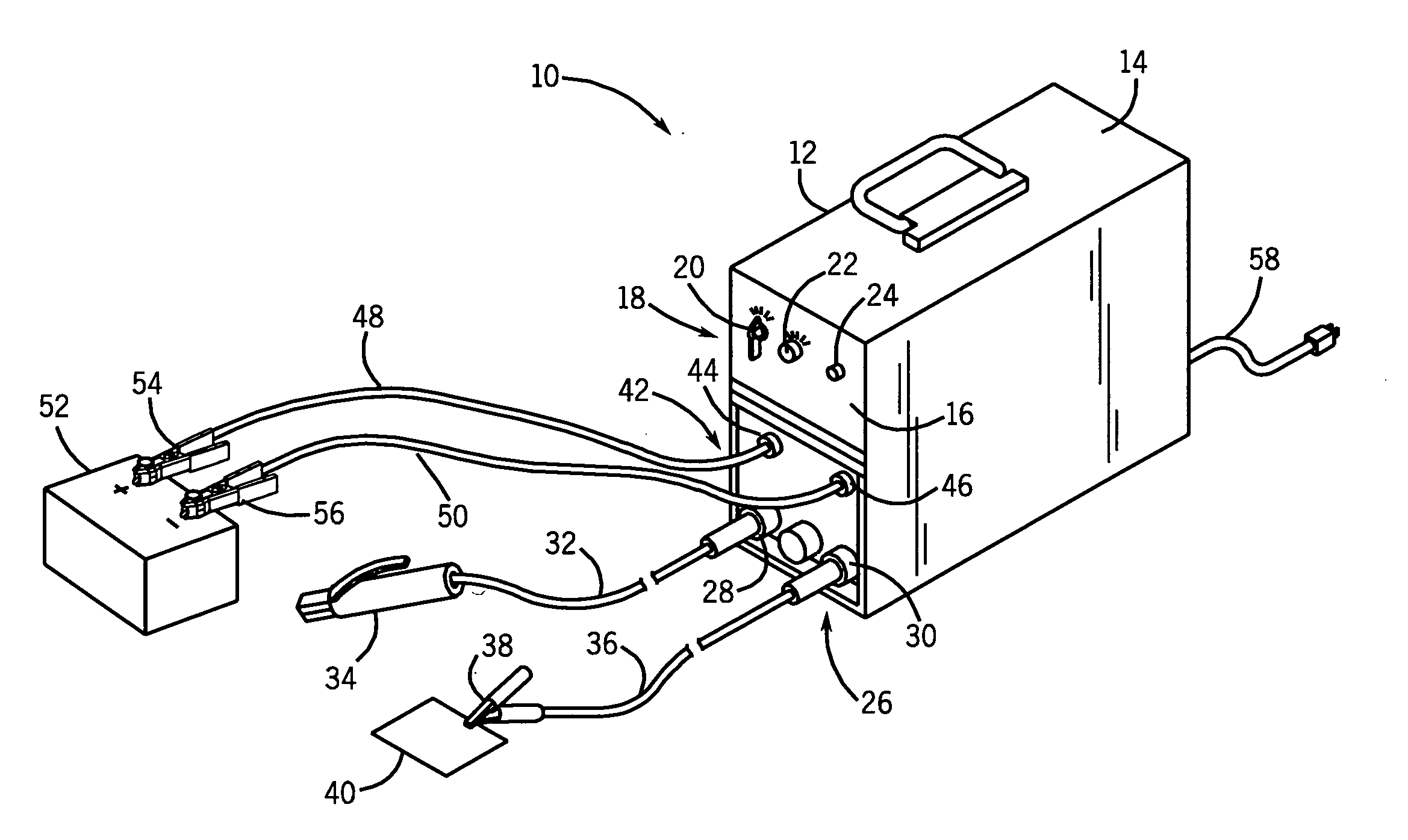
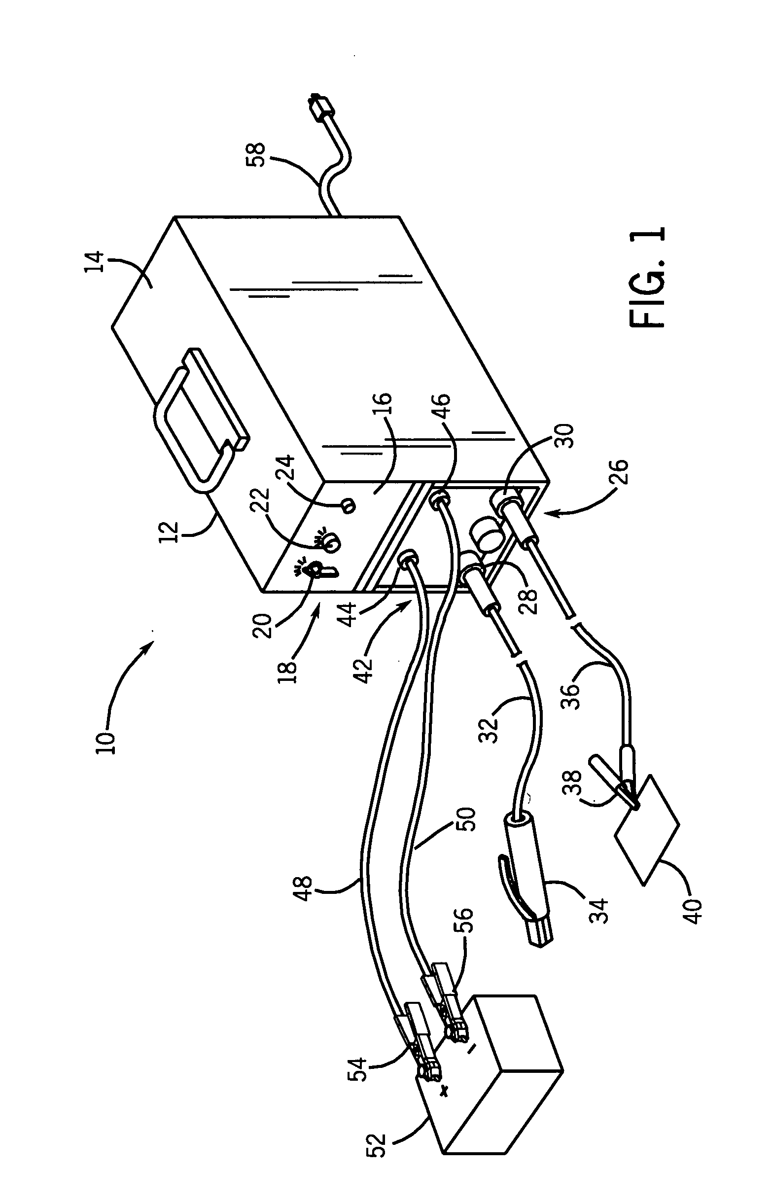
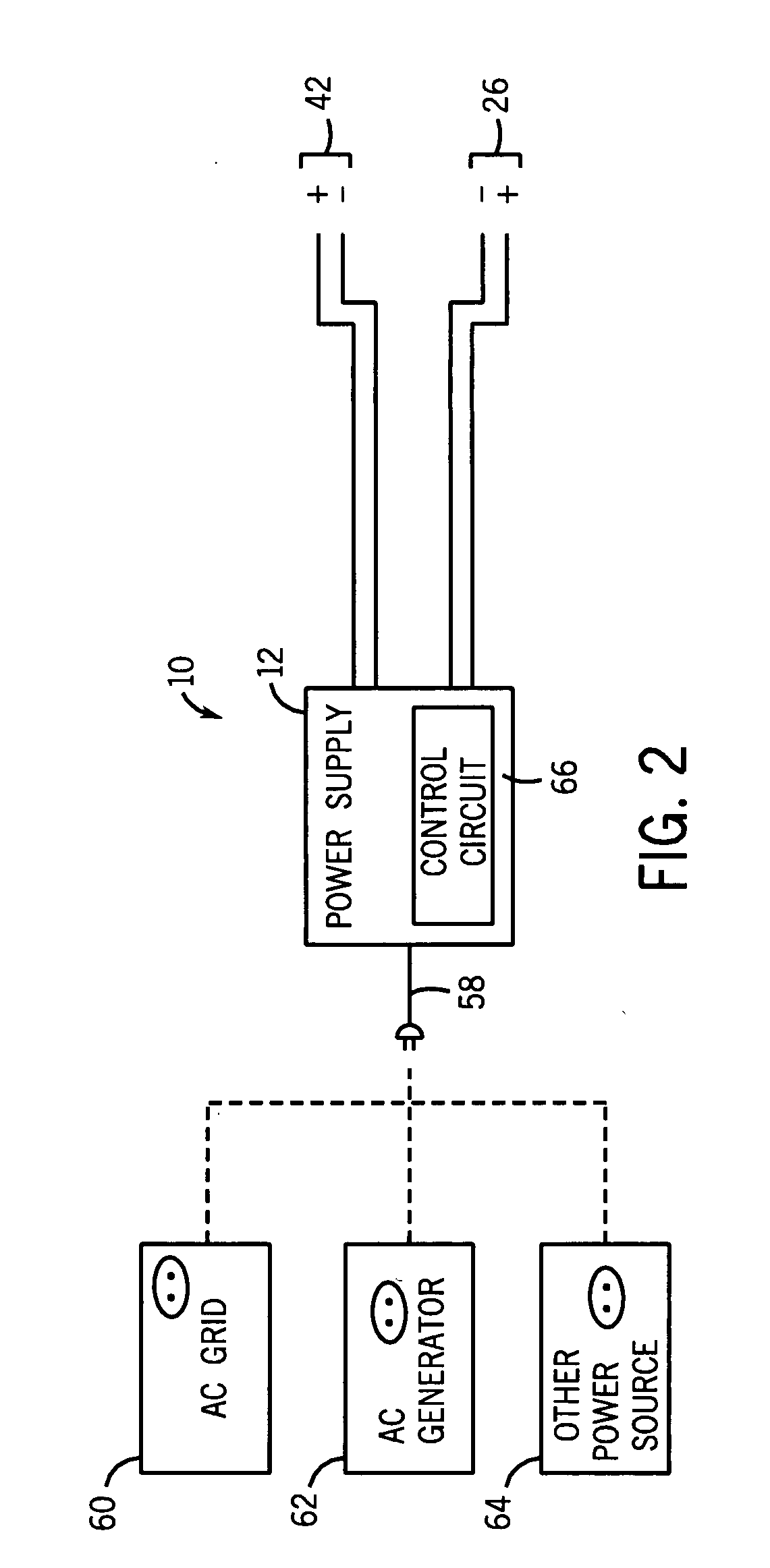
[0011]Referring now to the drawings, FIG. 1 illustrates an intelligent or smart welding / charging system 10 in accordance with one embodiment of the present technique. In other words, the system 10 does not blindly provide an output power for welding and / or charging, but rather the system 10 analyzes various parameters, executes various logic, and intakes sensed feedback to make an intelligent decision regarding the output. As discussed in detail below, the welding / charging system 10 includes a power supply with outputs for welding and charging. The charging outputs may also be used to jump start an engine driven device, such as an automobile. In certain embodiments, the welding and charging outputs are separate from one another. Further, the power supply includes control circuitry that provides a welding output and a charging output based on the selected configuration. For example, a user can select the voltage of the battery or device to be charged, or jump started, and the power s...


PUM

PropertyMeasurementUnit
poweraaaaaaaaaa
direct currentaaaaaaaaaa
temperatureaaaaaaaaaa

Abstract

A system, in one embodiment, may include a portable welder having a welding output, a charging output, a welding circuit coupled to the welding output; and a charging circuit coupled to the charging output. The charging circuit may be configured to automatically adjust power to the charging output based on a feedback associated with charging a battery.

Description

BACKGROUND[0001]The invention relates generally to welding systems and more particularly to portable welding systems including a charging output.[0002]Welding and cutting systems generally include a power supply configured to supply a current used in the operation of the respective system. In these systems, the current may be passed through, near, or around a work piece to weld or cut the work piece. Typically, the power supply receives alternating current (AC) power from a power grid and conditions the power for use in the specific system. Portable welding units generally include compact configurations that are maneuverable and can be plugged into various external AC power sources, such as an AC power grid, or an AC generator. The compact configuration of portable welding units enables an operator to easily transport the unit for welding and cutting in various locations.[0003]Welding units are generally configured to output power specifically for welding or cutting rather than othe...

Claims


Application Information

Patent Timeline
Patent Type & Authority Applications(United States)
IPC IPC(8): B23K9/10B23K9/067H02J7/00B23K9/073
CPCB23K9/1006H02J7/045B23K9/1062H02J7/04H02J7/00714H02J7/007182
Inventor BEESON, RICKFOSBINDER, DANIEL C.
Owner ILLINOIS TOOL WORKS INC
Why Eureka
Try Eureka