Assembly and method for magnetization of permanent magnet rotors in electrical machines

a technology of permanent magnet rotors and electrical machines, which is applied in the direction of rotating magnets, synchronous machines with stationary armatures, magnetic bodies, etc., can solve the problems of cumbersome process of assembly of rotors from pre-magnetized permanent magnet segments

Inactive Publication Date: 2009-01-08
GENERAL ELECTRIC CO
View PDF3 Cites 32 Cited by
  • Summary
  • Abstract
  • Description
  • Claims
  • Application Information

AI Technical Summary

Problems solved by technology

Assembly of rotors from pre-magnetized permanent magnet segments is often a cumbersome process, especially in larger electrical

Method used


Image

  • Assembly and method for magnetization of permanent magnet rotors in electrical machines
  • Assembly and method for magnetization of permanent magnet rotors in electrical machines
  • Assembly and method for magnetization of permanent magnet rotors in electrical machines

Examples


Embodiment Construction

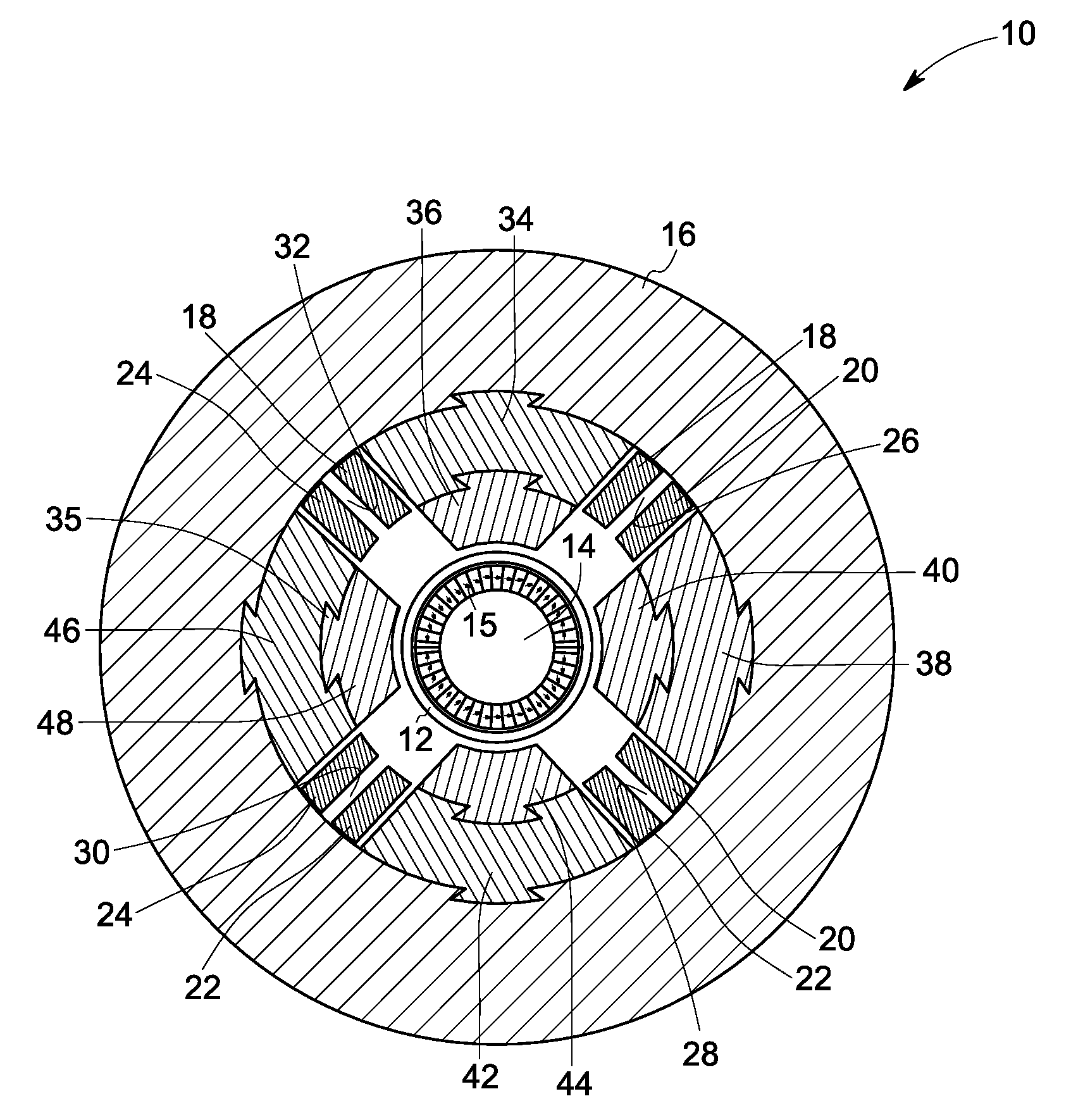
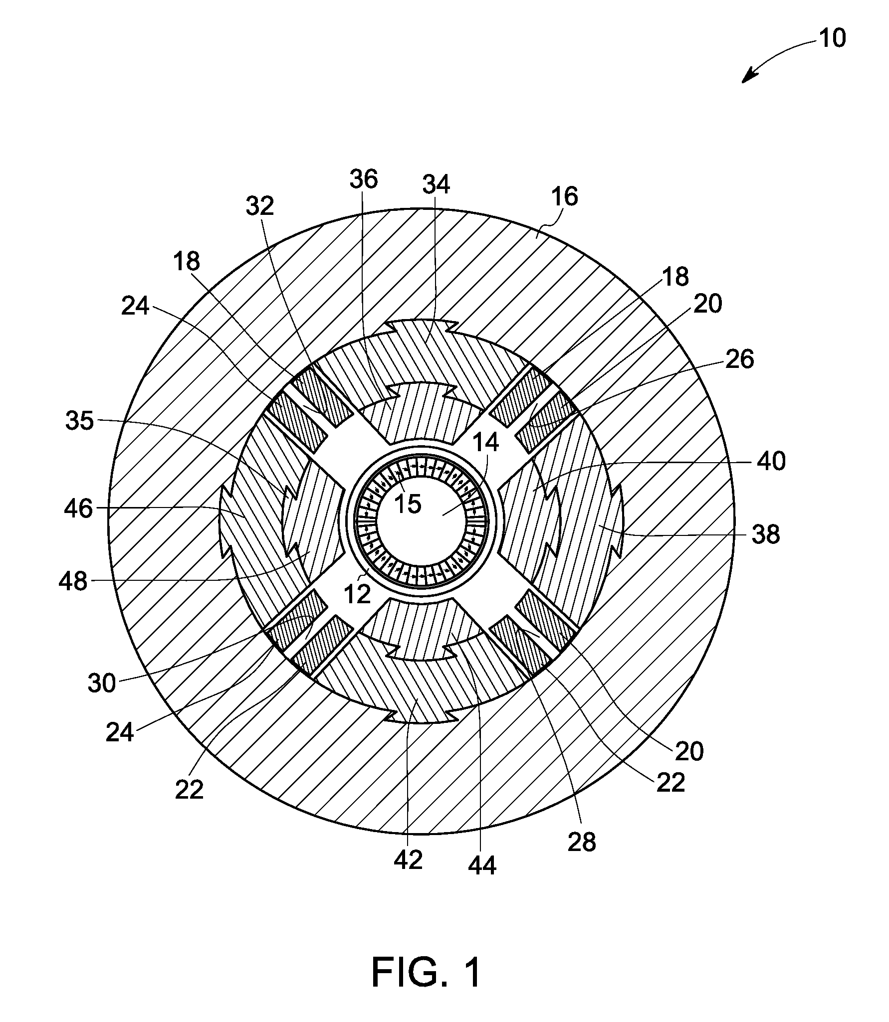
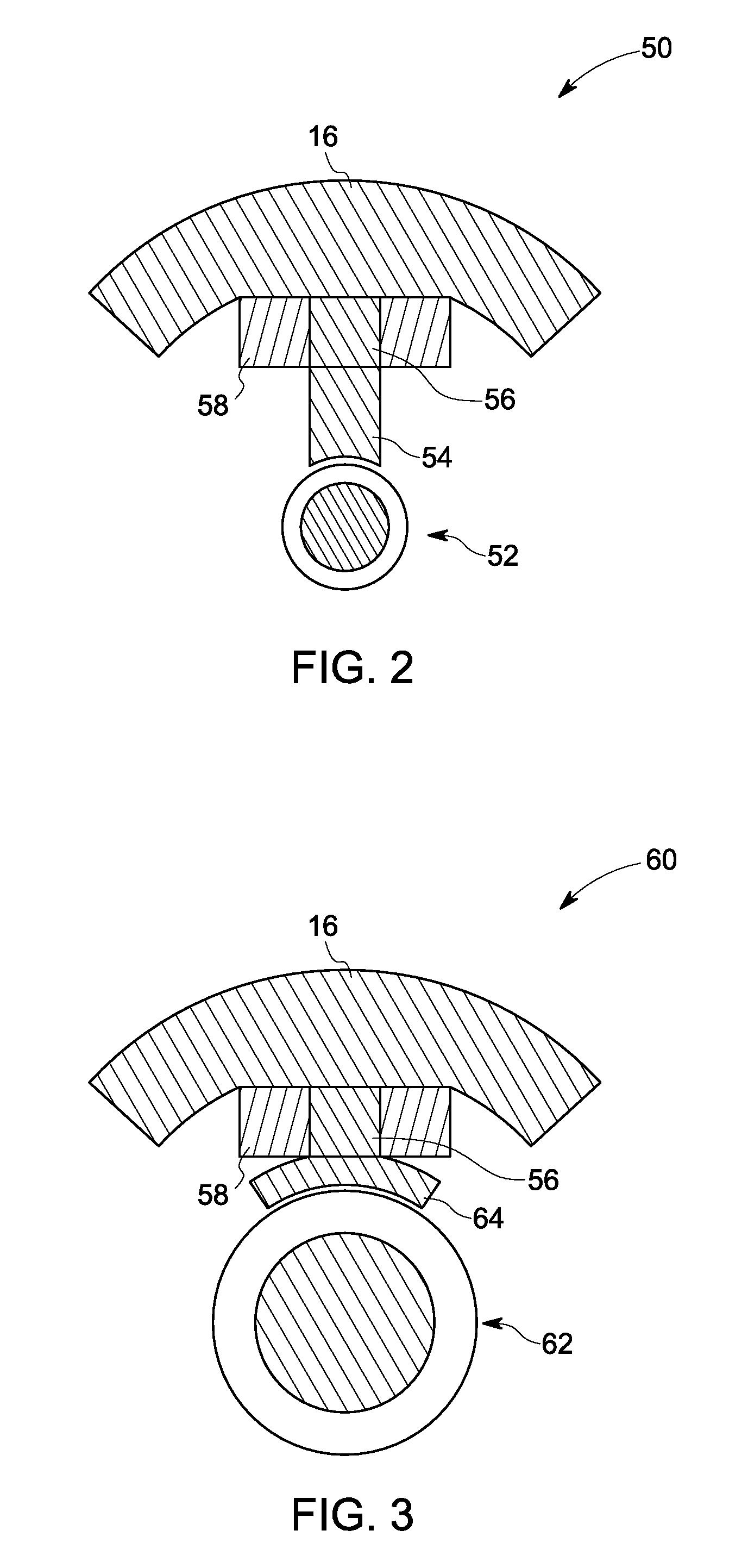
[0013]The embodiments disclosed herein provide an assembly and method for magnetizing an electrical machine rotor. A simple magnetization method is provided for an entire assembled rotor in a multi-pole magnetizer. FIG. 1 illustrates a magnetizing fixture 10 (herein referenced as a “magnetizer”) for a rotor 12 of an electrical machine. Magnetizer 10 comprises a magnetizing yoke 16 (or “core”) which comprises a plurality of pole-pieces 34, 38, 42, and 46 extending therefrom and a plurality of magnetizing (or “excitation”) coils 18, 20, 22, and 24 wound around the pole-pieces of the magnetizing yoke. In a first embodiment, at least some of the plurality of pole-pieces comprise a cobalt alloy. In a second embodiment, the plurality of coils comprise hollow tube coils (described in more detail with reference to FIG. 4) configured to allow a flow of a coolant therethrough. In a third embodiment, the pole-pieces each comprise a fixed pole-piece portion 34 and an interchangeable pole-piece ...


PUM

PropertyMeasurementUnit
Percent by massaaaaaaaaaa

Abstract

A magnetizer for a rotor of an electrical machine is provided. The magnetizer includes a magnetizing yoke and coils wound around the magnetizing yoke. The magnetizing yoke includes multiple pole-pieces extending therefrom, and at least some of the pole-pieces include a cobalt alloy.

Description

BACKGROUND[0001]The subject matter disclosed herein relates generally to electrical machines, particularly to electrical machines having permanent magnet type rotors. Specific embodiments relate to an assembly and method for magnetization of permanent magnet segments in such rotors.[0002]An electrical machine generally includes a rotor disposed within a stator and is used either as a motor to convert electrical power to mechanical power or as a generator to convert mechanical power to electrical power. Certain electrical machines use permanent magnet type rotors that reduce the size and enhance the overall efficiency of the machine. A permanent magnet rotor generally includes an annular permanent magnet disposed over a rotor spindle. In certain embodiments, the permanent magnet is a monolithic hollow cylindrical member. In larger machines, the permanent magnet is generally formed by assembling a plurality of permanent magnets around a rotor spindle. High-speed electrical machines ma...

Claims


Application Information

Patent Timeline
IPC IPC(8): H02K21/12H02K9/19
CPCC22C19/07C22C30/00H02K15/03C22C38/12H01F13/003C22C38/10
Inventor STEPHENS, CHARLES MICHAELKAMINSKI, CHRISTOPHER ANTHONYWEEBER, KONRAD ROMANYAGIELSKI, JOHN RUSSELL
Owner GENERAL ELECTRIC CO
Why Eureka
Try Eureka